Building manual BrailleRAP-SP
Woodbox assembling
Material:
- FACE (5mm laser cut plywood).
- BACK ().5mm laser cut plywood
- BOTTOM (5mm laser cut plywood).
- LEFT_SIDE (5mm laser cut plywood).
- RIGHT_SIDE (5mm laser cut plywood).
- wood glue
- Blue tape
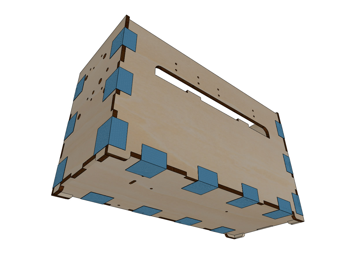
- Get the 5 elements : FACE, BACK, LEFT_SIDE, RIGHT_SIDE et BOTTOM.
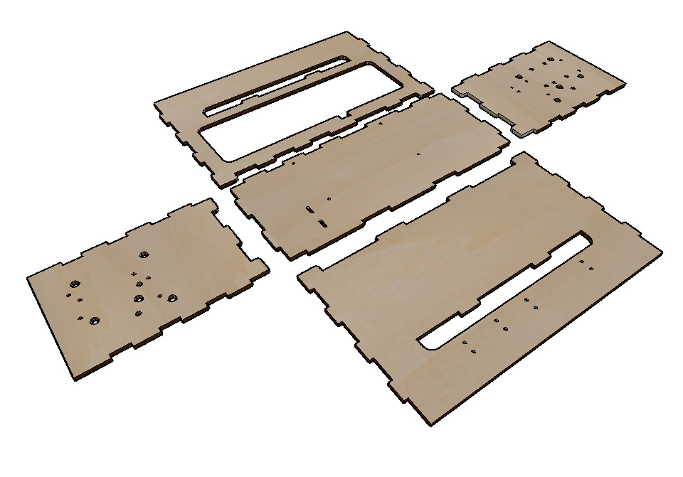
- Glue the notches, assemble the 5 parts and hold them in place with painter’s tape the drying time recommended by the manufacturer.
Collage of trap blockers
Material:
- Assembled wood box.
- 3 wooden discs recovered from the laser cutting of the lid.
- wood glue
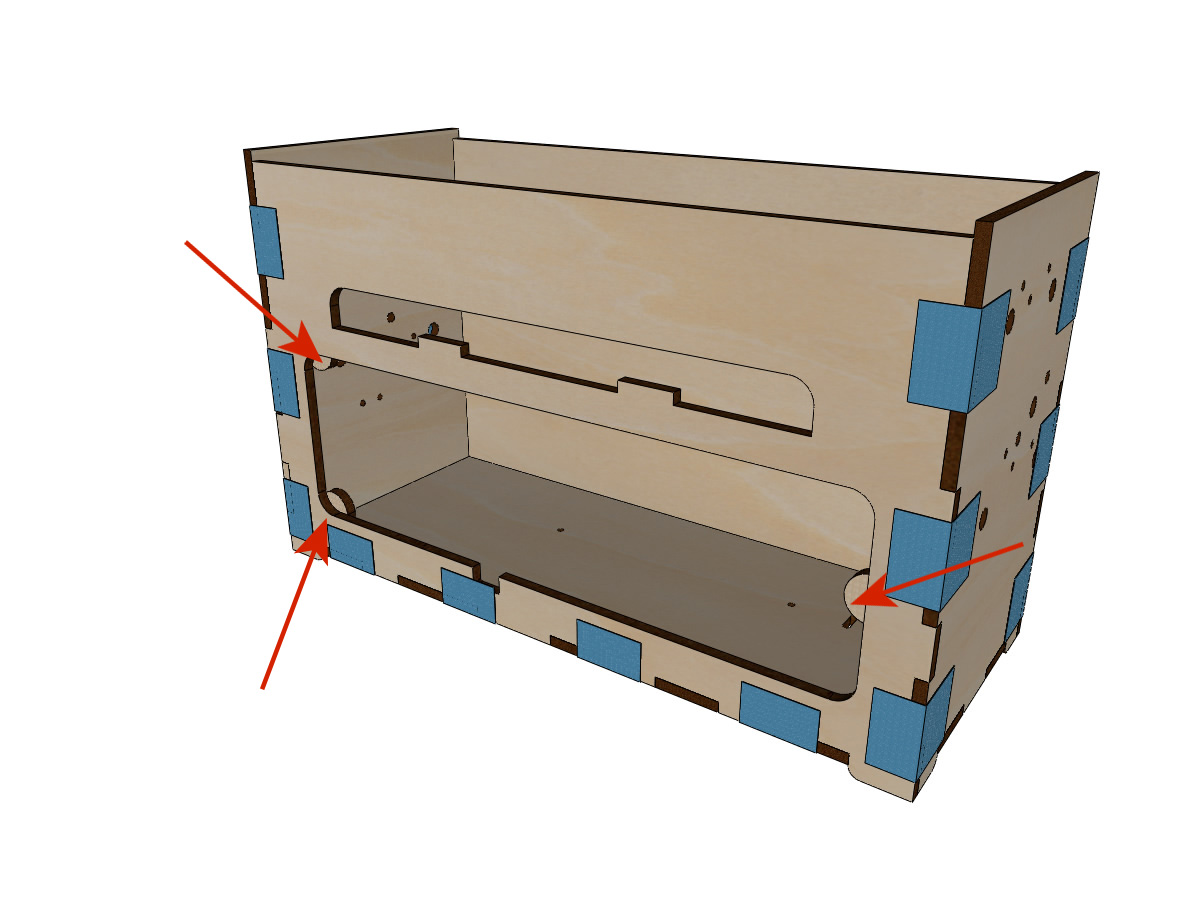
- Glue the 3 wooden discs on the back cover inside the crate. These discs will hold the access hatch inside the machine.
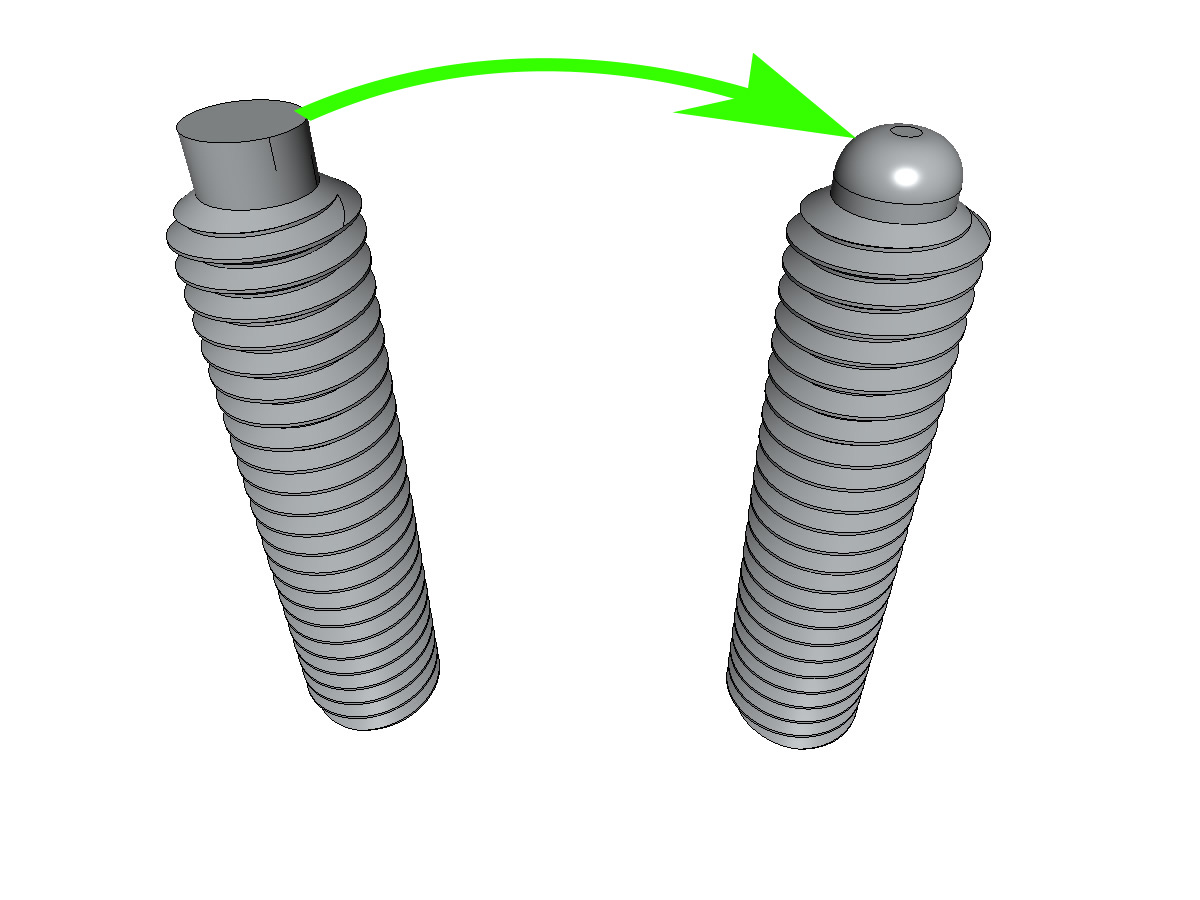
Preparation of the male needle
equipment:
- 1 metal file or sand paper or a Dremel
- 1 vis sans tête M3-16 bout téton
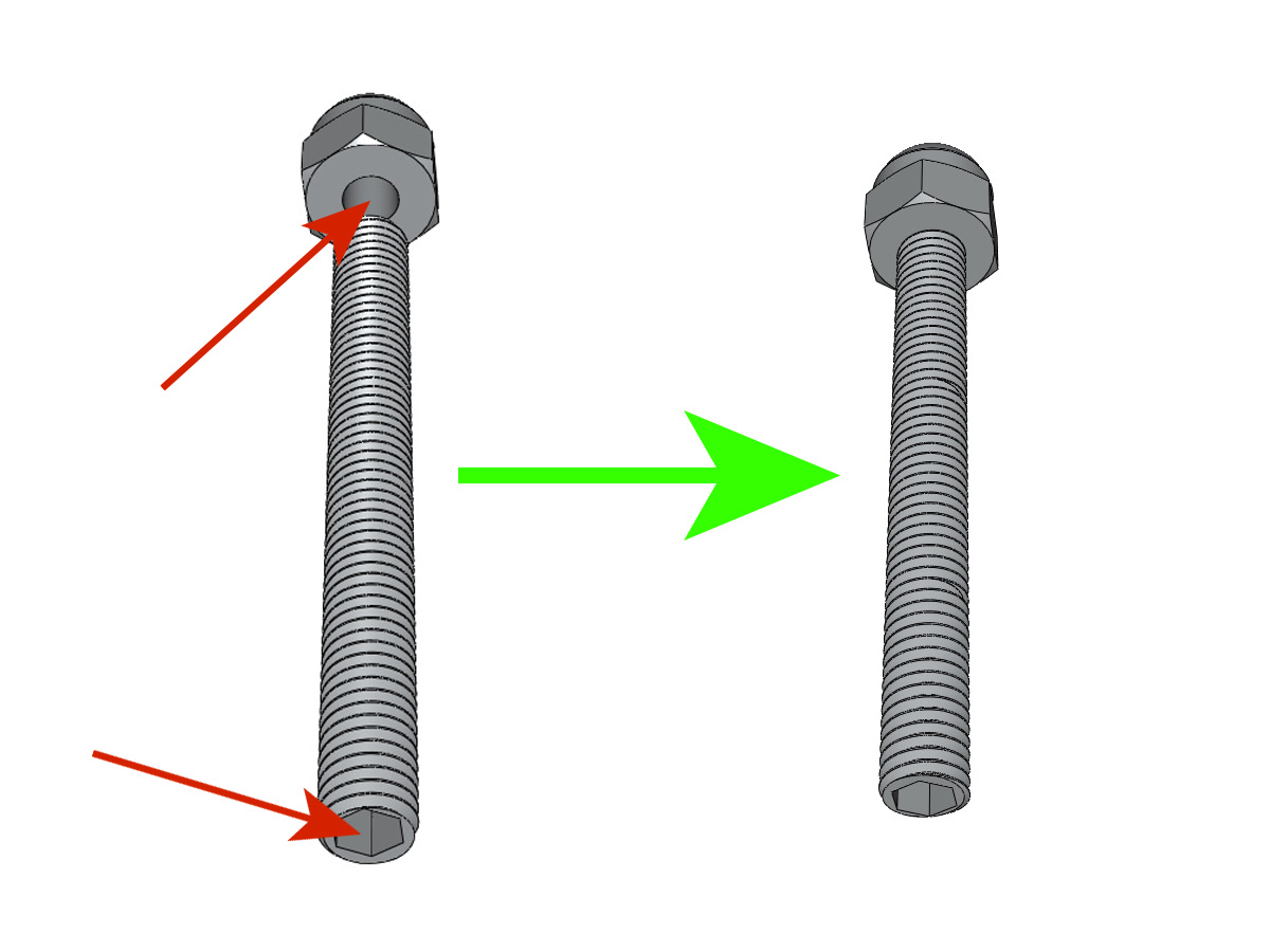
- File the edge of the nipple to obtain a profile approaching that illustrated.
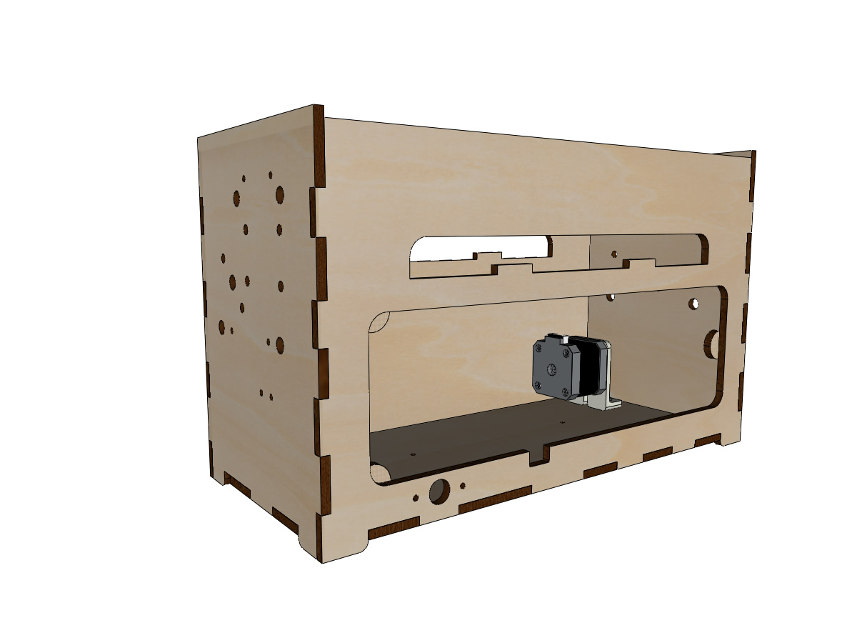
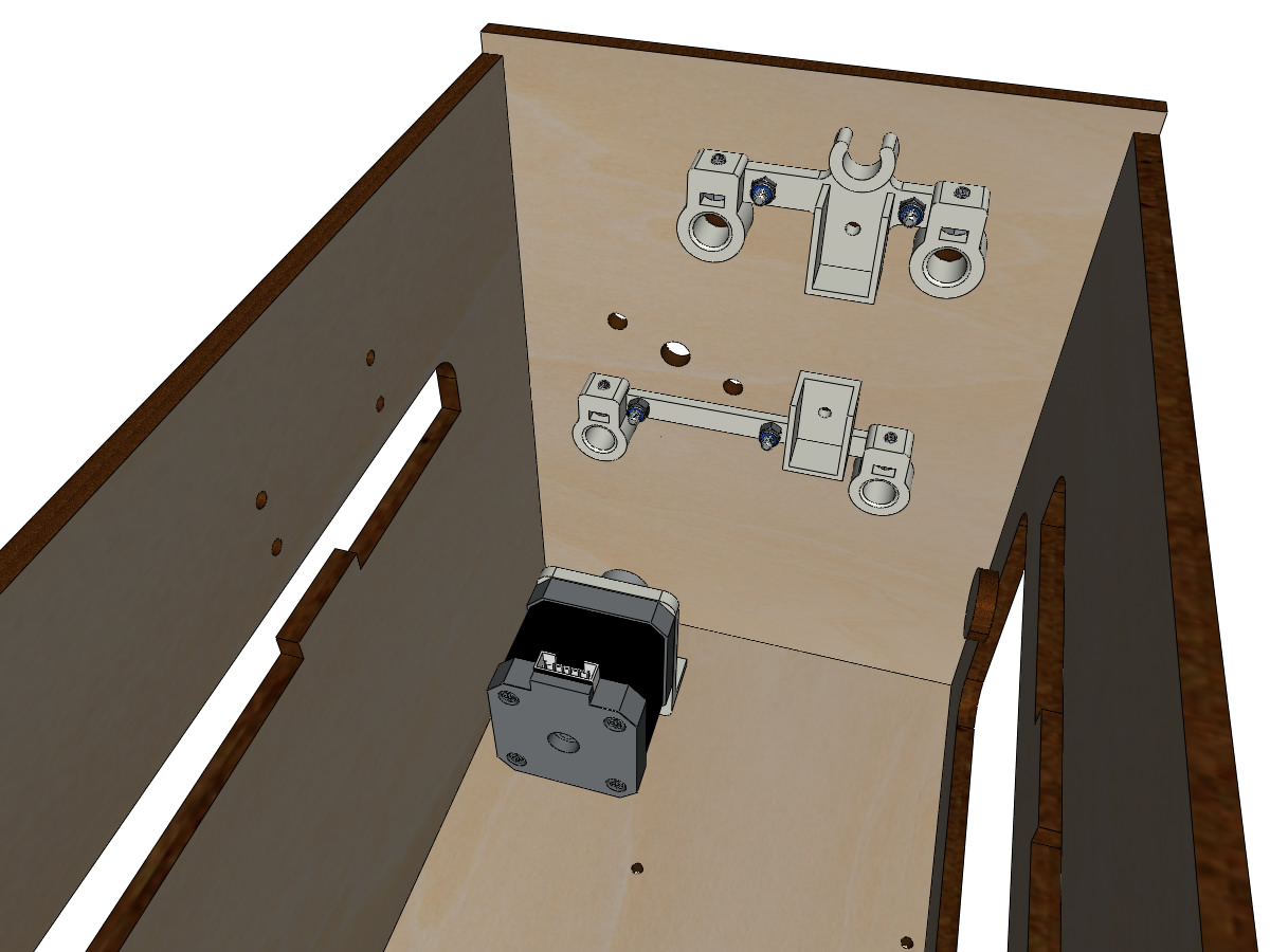
Y Motor
equipment:
- 3D printed parts : YMOTOR_support_200 ou YMOTOR_support_220 (selon la longueur de la courroie fermée GT2)
- 1 Nema 17 motor
- 1 pulley GT2 20 teeth 5mm bore
- 4 screw M3-8
- 2 NYLSTOP M3
- 2 screws M3-12
- 2 wide M3 washers
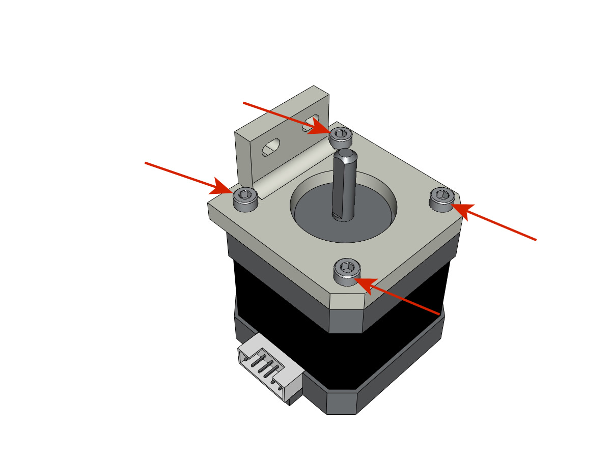
- Screw the pulley onto the motor shaft, making sure that at least one of the two screws is in front of the flat part of the motor shaft and that the teeth of the pulley are facing towards the motor.
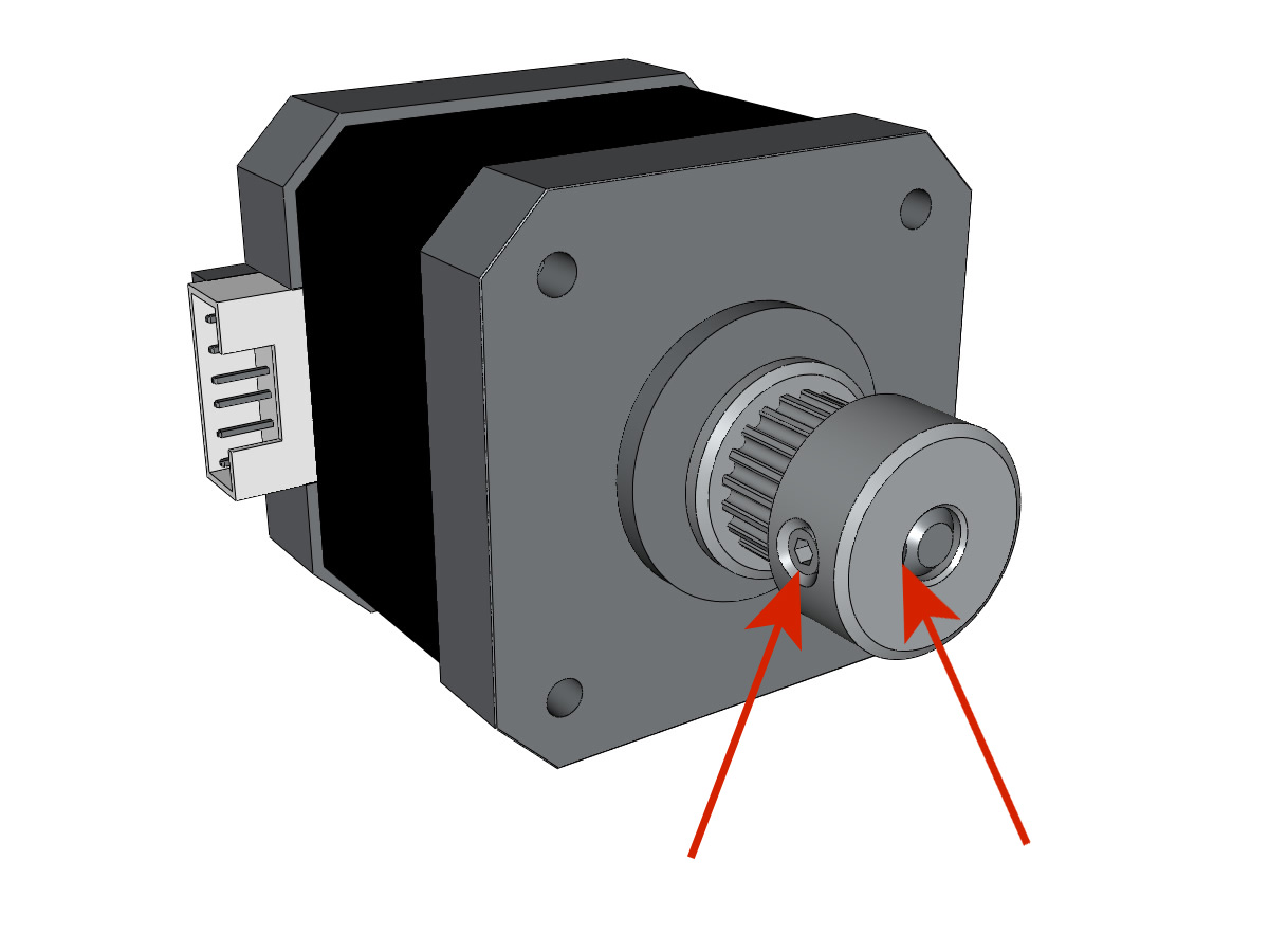
- Mount the motor on its support with the 4 screws M3-8 making sure that the connector is in the position corresponding to the illustration.
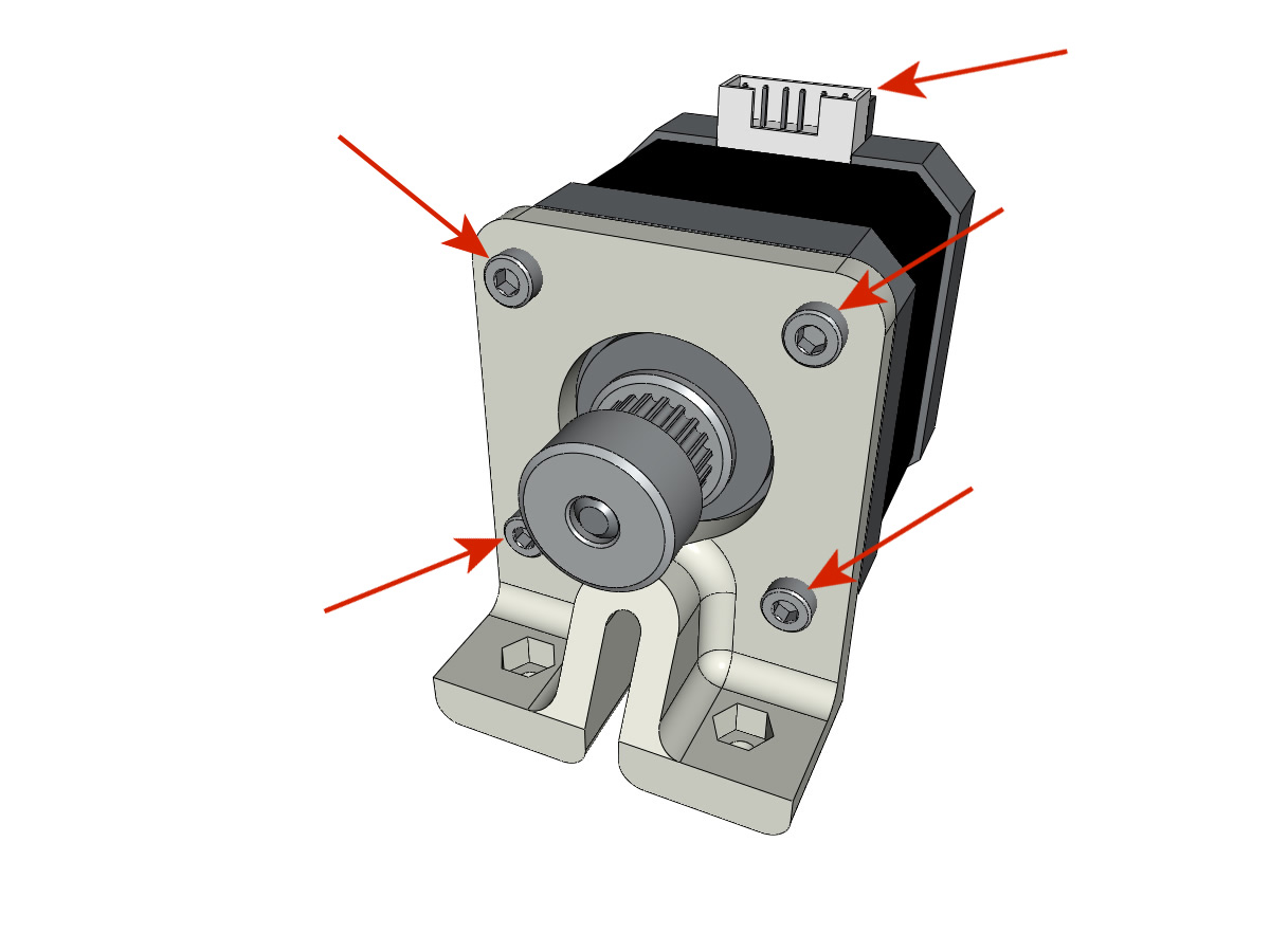
Attention
The illustration shows a motor support provided for a belt of 200mm but the mounting is the same with a motor support provided for a belt of 220mm.
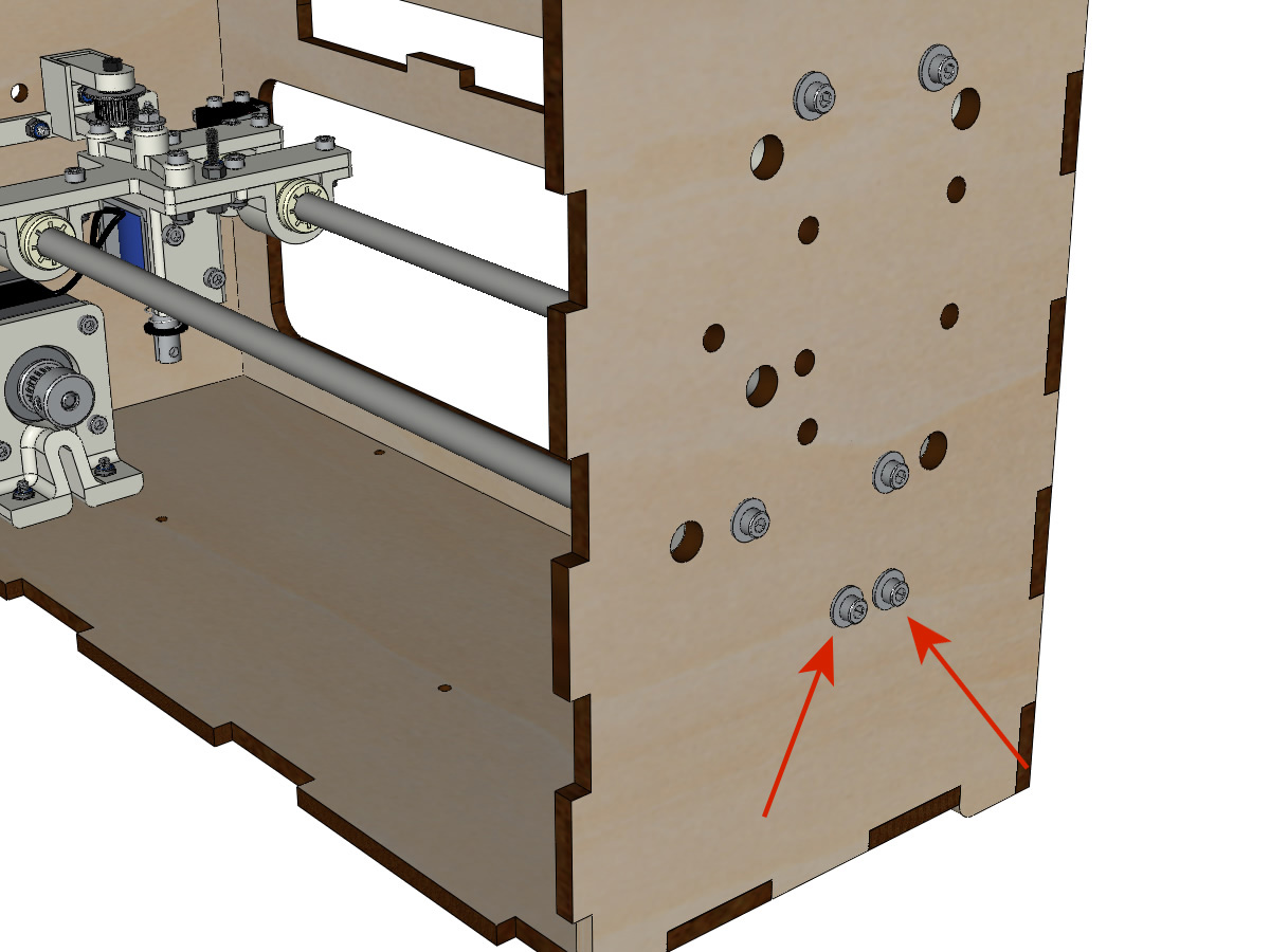
- Insert the NYL M3 nuts into the engine mount.
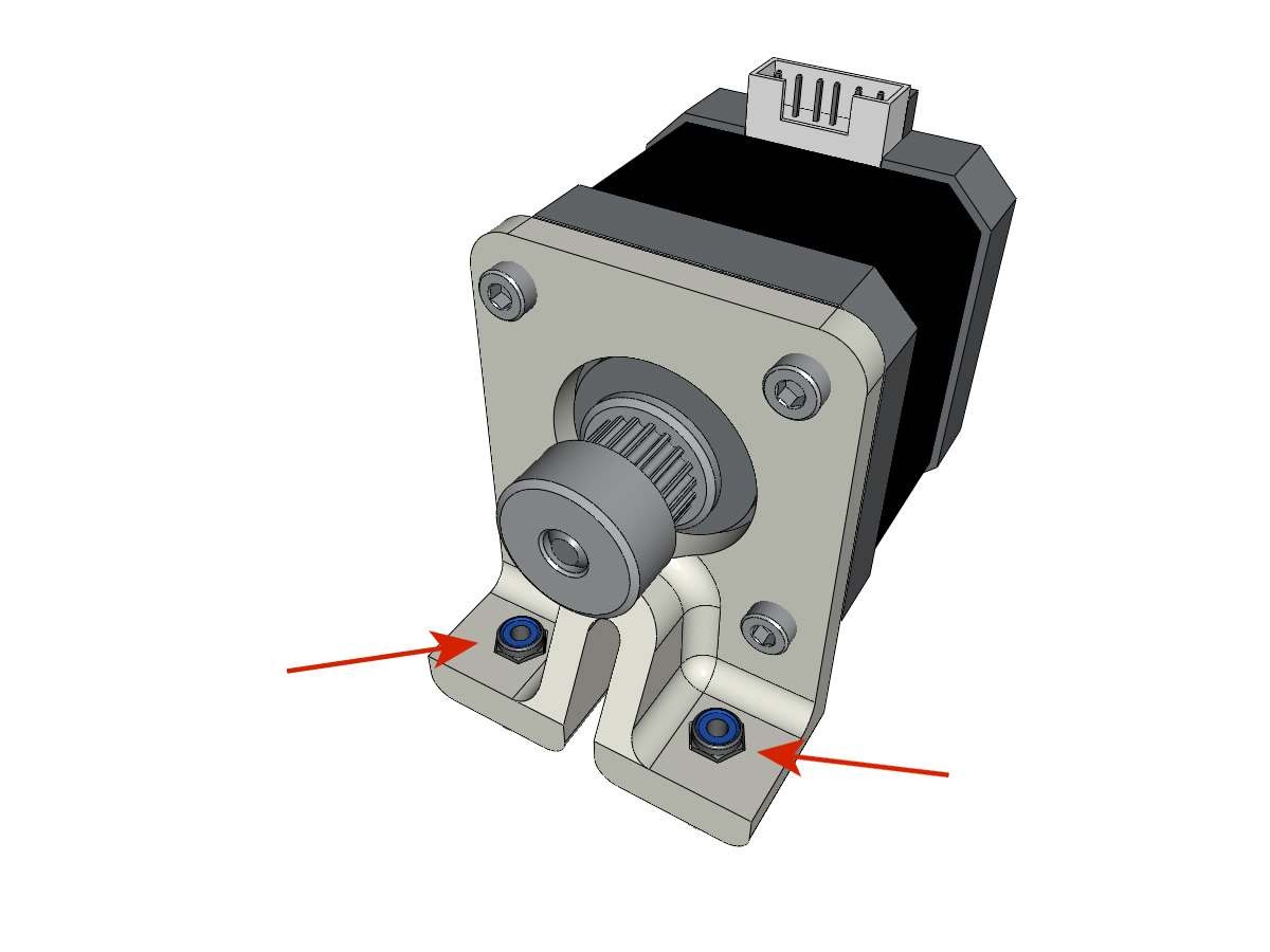
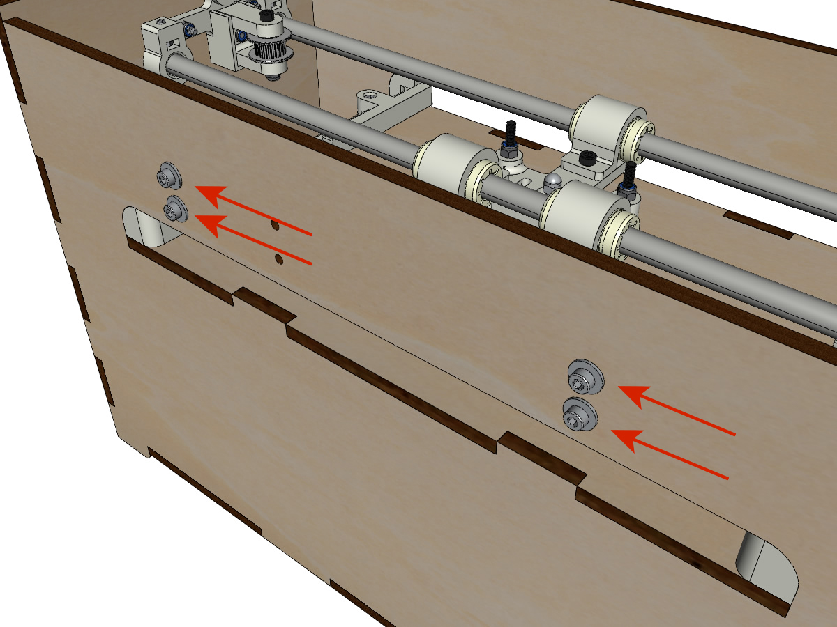
- Insert the screws and washers from the outside and screw the support onto the crate so that it can still slide in the oblong holes.
Preparation of axis supports
- 3D printed part : BOTTOM_AXIS_left
- 3D printed parts : BOTTOM_AXIS_right
- 3D printed parts : TOP_AXIS_left
- 3D printed parts : TOP_AXIS_right
- 1 8mm drill
- 8 M3 nuts
- 8 M3-12 screw
Attention
192/5000 Depending on the print quality of the plastic parts, make sure that the 8mm bars can slide easily into their housings. If necessary, drill the hole with a drill of 8.
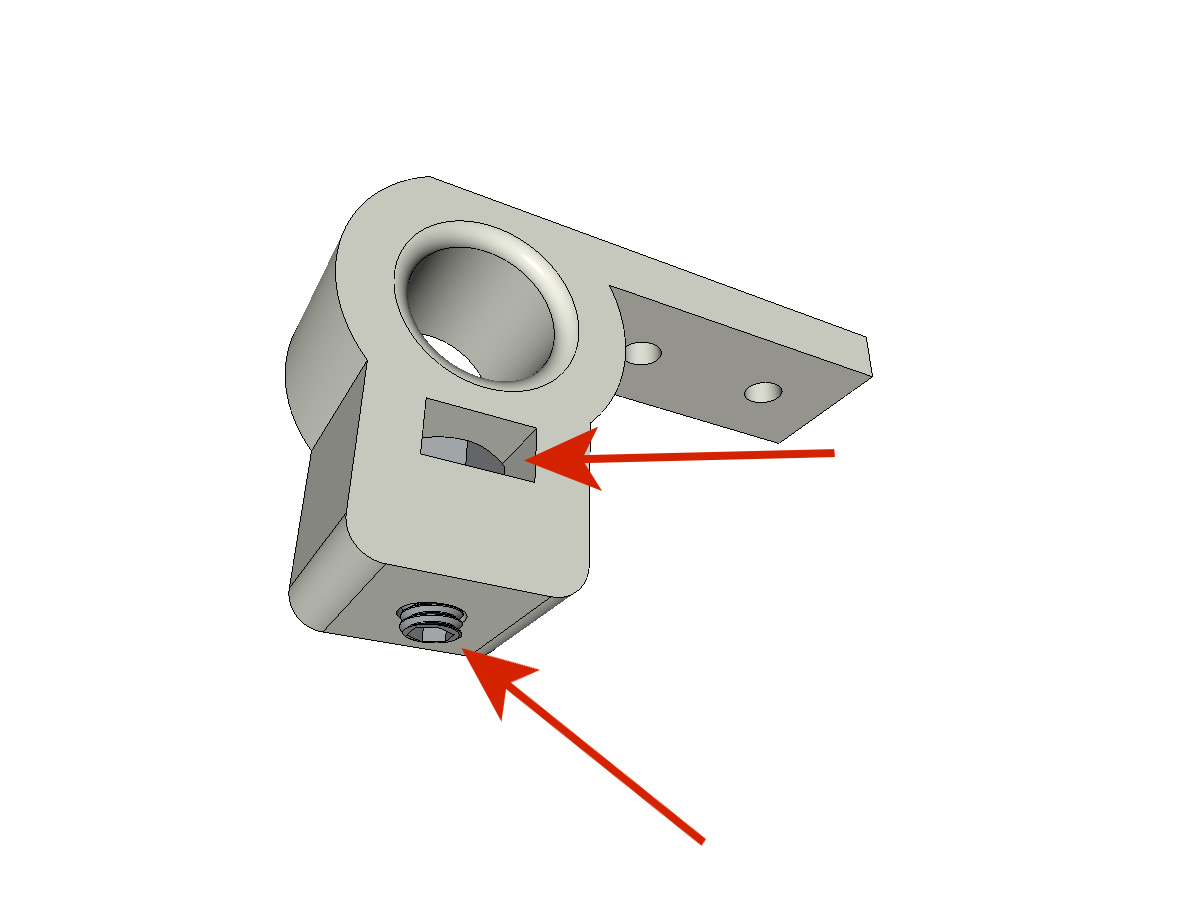
- Pour chacune des 4 pièces, introduire un écrou M3 dans les trous rectangulaires. Visser les vis M3-12.
- The end of the screw must not protrude in the passage of Ø 8mm bars.
38/5000 Fixing the LEFT supports of the axes
equipment:
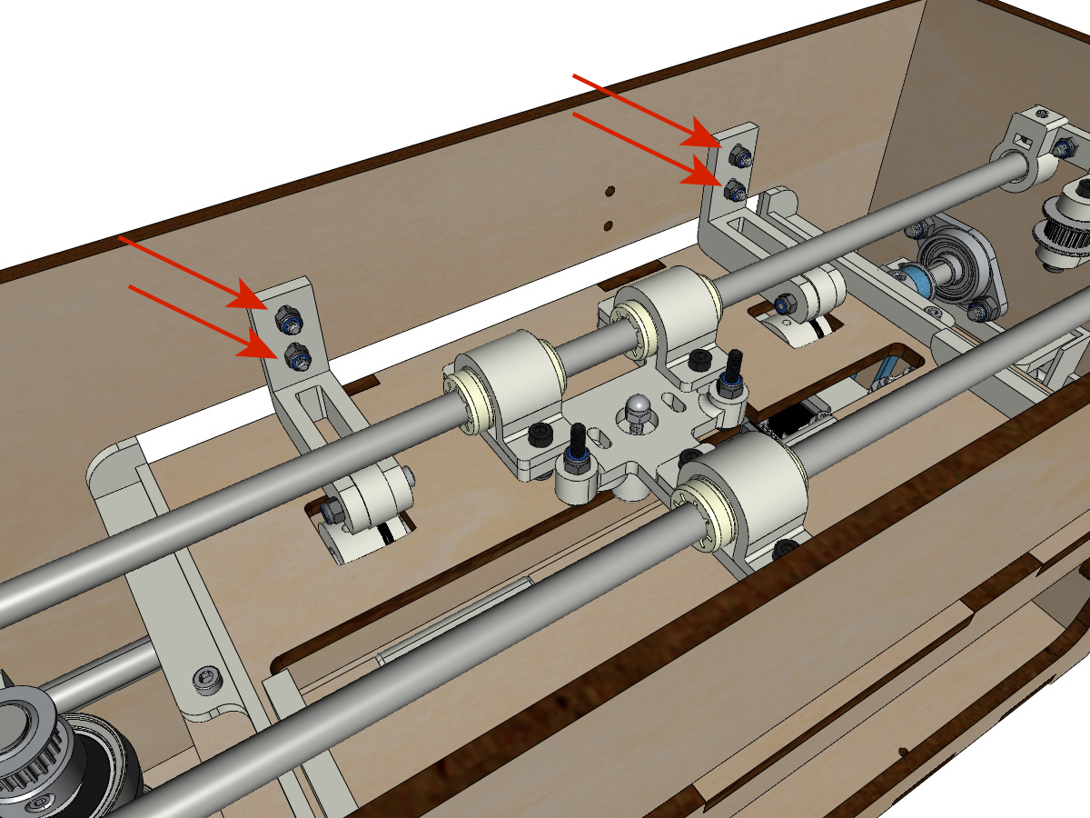
- Fix the supports of axis on the box the BOTTOM_AXIS_left and TOP_AXIS_left on the left leaving a little game (screw + washer outside and nut inside). The screws will be tight when the assembly is in place.
Fixing the RIGHT supports of the axes
equipment:
- Pièce(s) imprimée(s) en 3D : BOTTOM_AXIS_right
- ** 3D printed parts **: TOP_AXIS_right prepared with nut and grub screws (see Preparation of axle supports)
- 4 BTR screws M3-14
- 4 wide M3 washers
- 4 M3 NYL nuts
- Fixer les supports d’axe sur la caisse le BOTTOM_AXIS_right (attention à la position du repère) et TOP_AXIS_right à droite en laissant un peu de jeu (vis+rondelle à l’extérieur et écrou à l’intérieur). Les vis seront serrées quand l’ensemble sera en place.
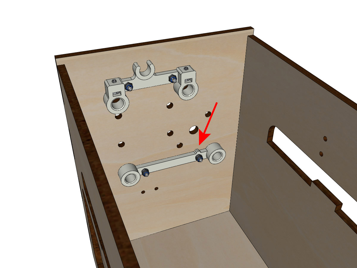
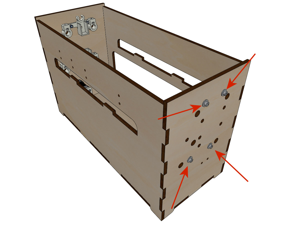
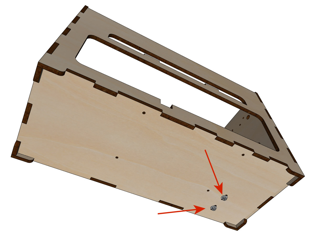
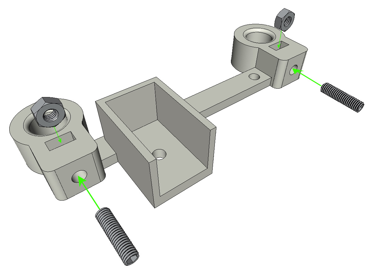
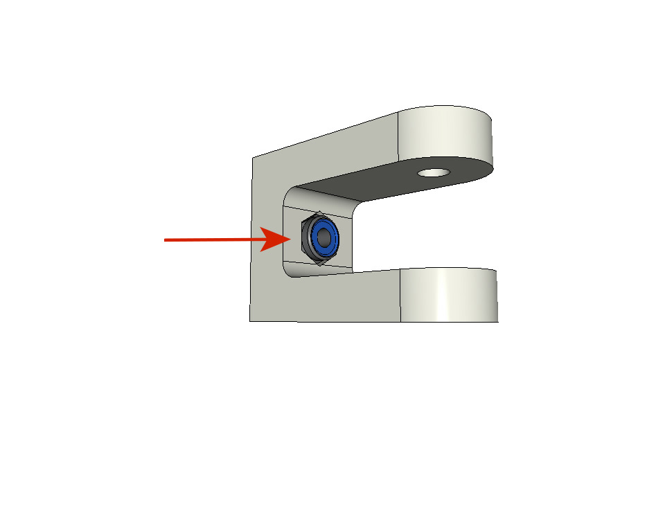
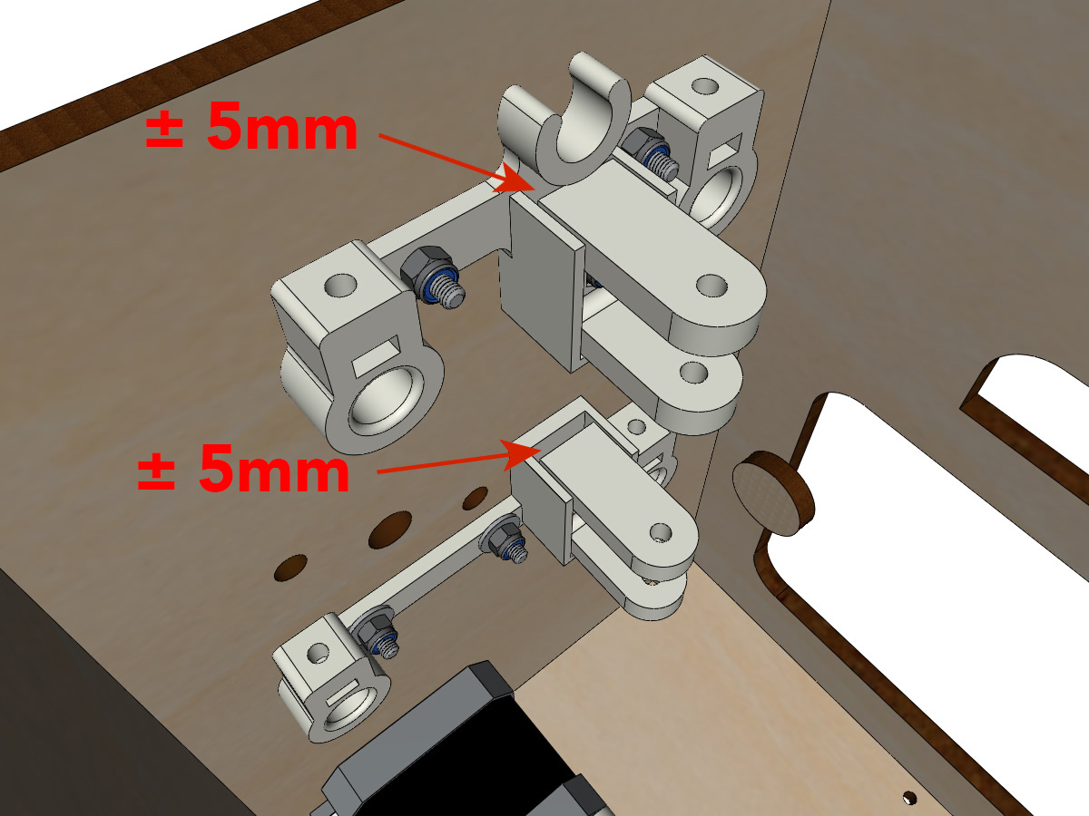
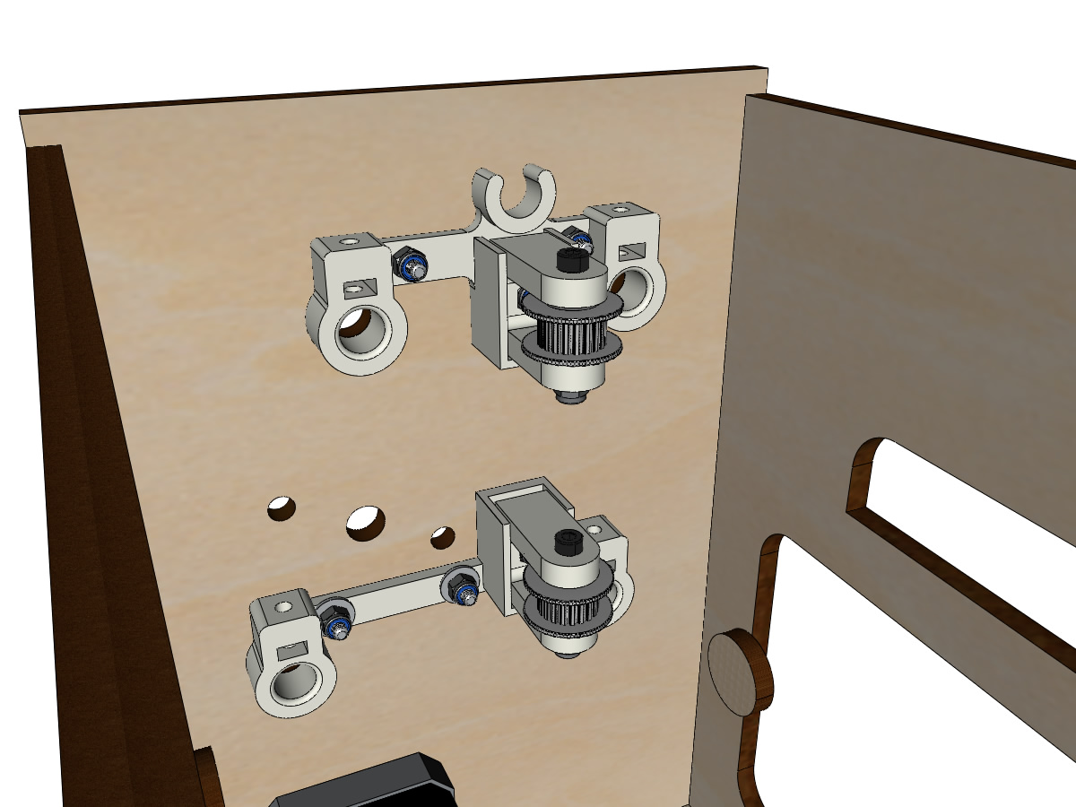
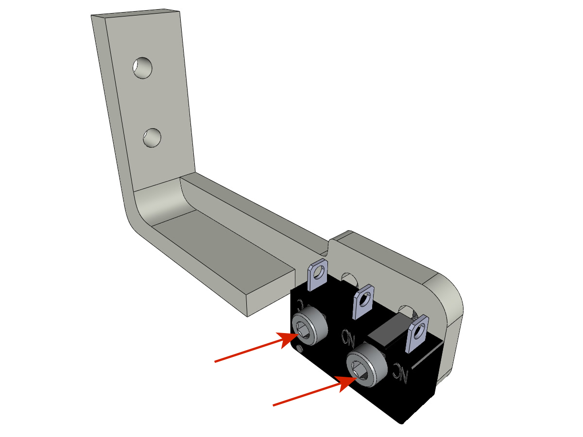
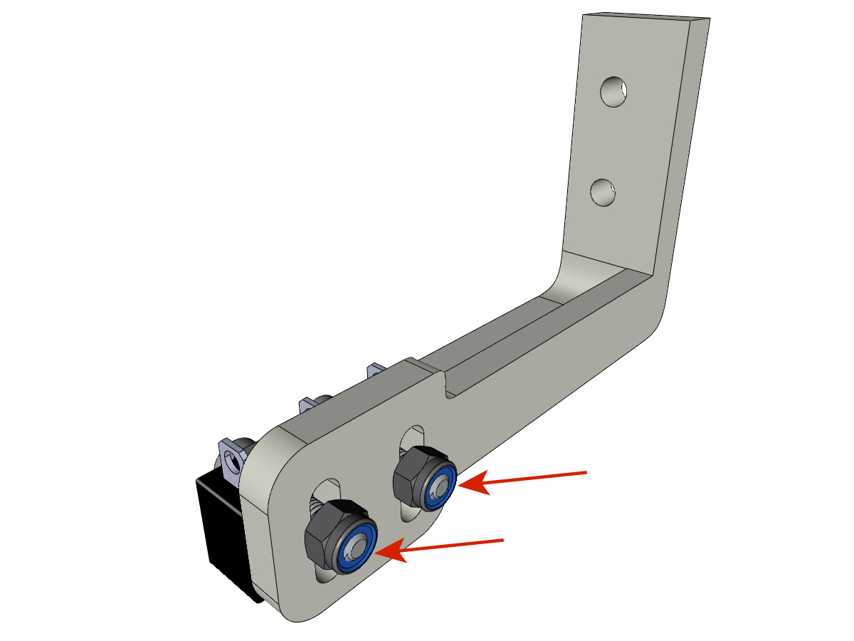
Fastening the belt tensioners
equipment:
- ** 3D printed parts ** : 2 x DRIVEN_PULLEY_housing
- 2 M3-20 BTR screw
- 2 wide M3 washers
- 2 NYLSTOP M3
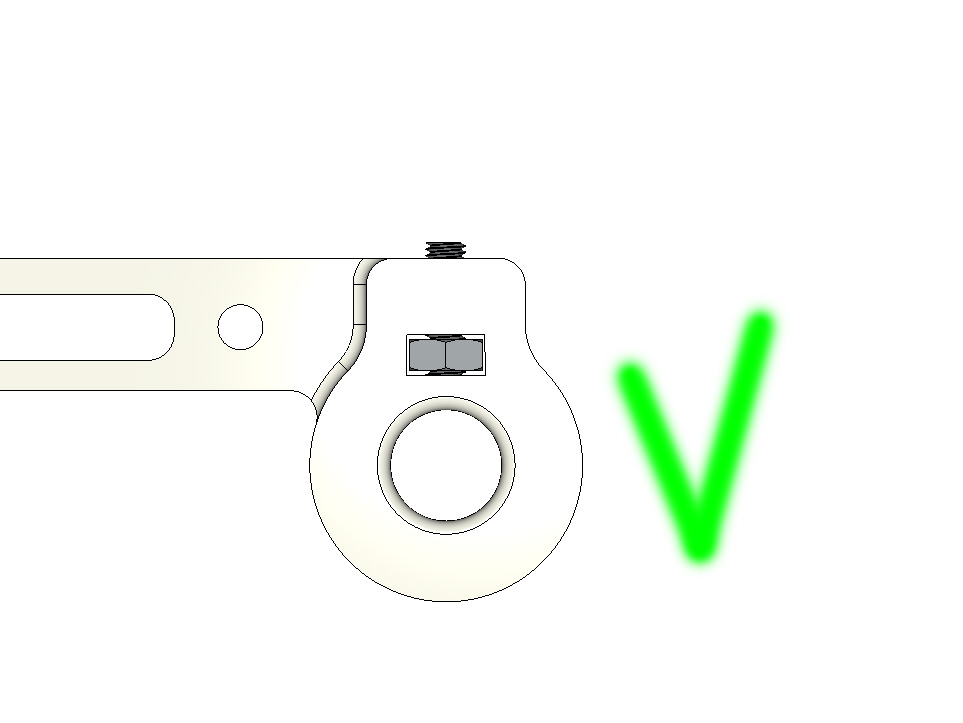
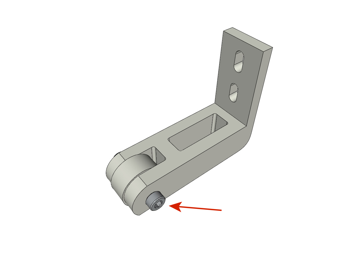
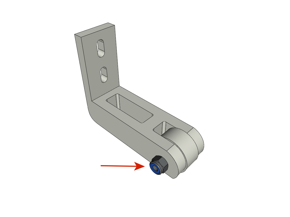
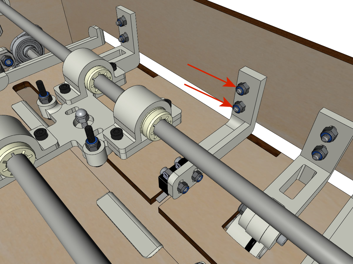
- Insert a NYL M3 nut into its housing and secure the DRIVEN_PULLEY_housing with a M3-20 screw and washer.
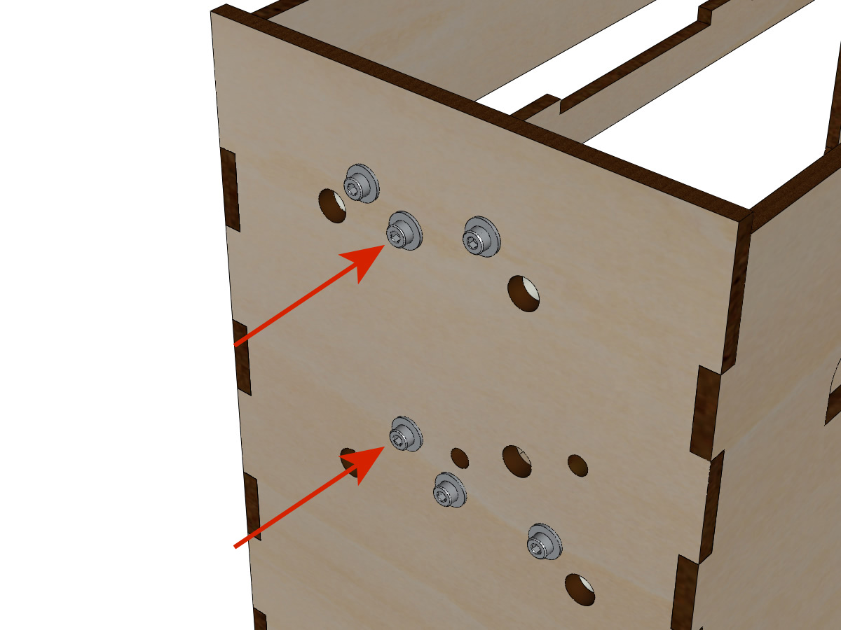
- Leave a gap of ± 5mm.
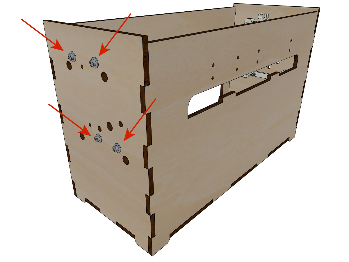
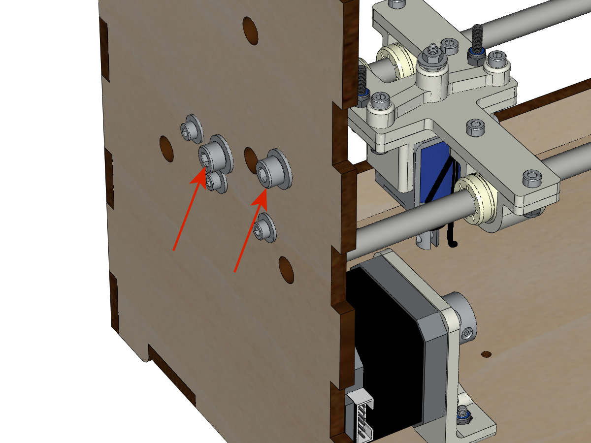
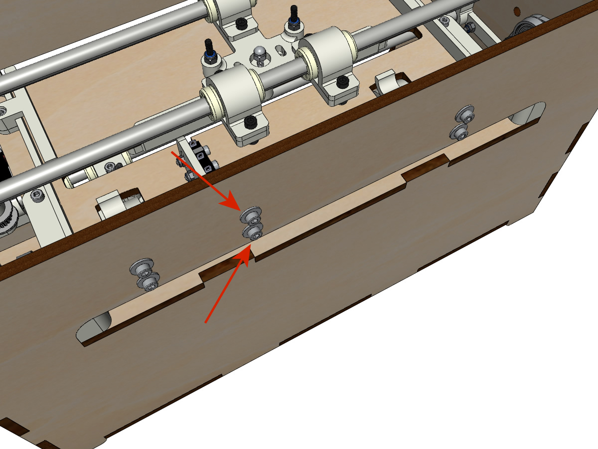
Laying free return pulleys
equipment:
- 2 free pulleys 20 teeth 3mm bore
- 2 M3-25 BTR screw
- 2 NYLSTOP M3
- Start by inserting the pulley then the M3-25 screw. Screw with a NYL M3 nut without tightening too much.
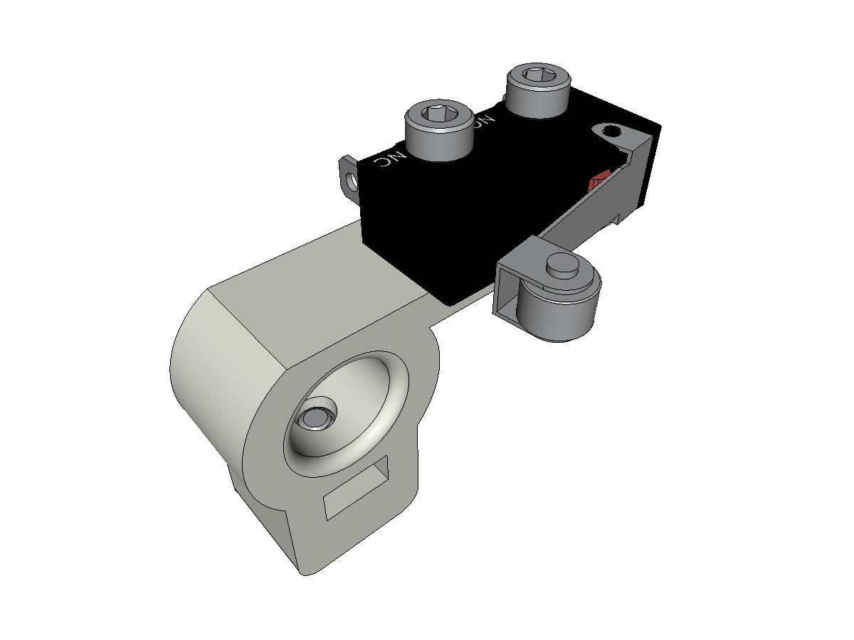
Mounting the limit switch X
equipment:
- ** 3D printed parts ** : SWITCH_X_support
- 1 wired limit switch (see wiring of the limit switches)
- 1 vis sans tête M3-8
- 1 M3 nuts
- 2 vis M2.5-14 Michel, on t’a mis des M2.5-14 ;)
- 2 M2.5 nuts
Note
Changer l’image avec support interrupteur (nouveau modèle).
- Introduire un écrou M3 et visser une vis sans tête M3-8.
- Screw the limit switch to its support (SWITCH_X_support) using M2.5-12 screws and M2.5 nuts.
Note
The limit switch is shown not wired but must be wired before installation.
Preparation of the electromagnet
equipment:
- 1 electromagnet
- 1 spacer 18mm
- 1 set screw M3-12 needle punched (see Preparing the male needle)
- 1 M3 nuts
- 1 M3 medium washer
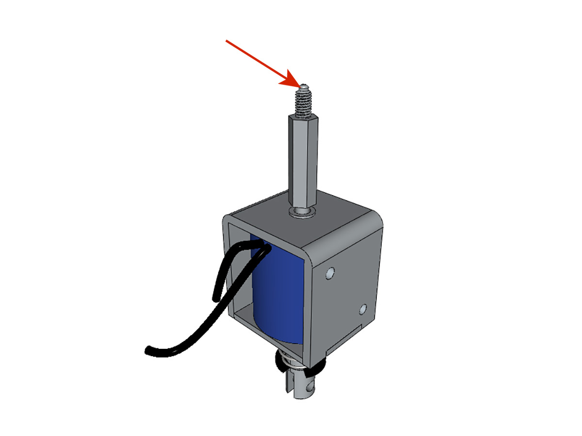
- Screw the spacer all the way onto the electromagnet.
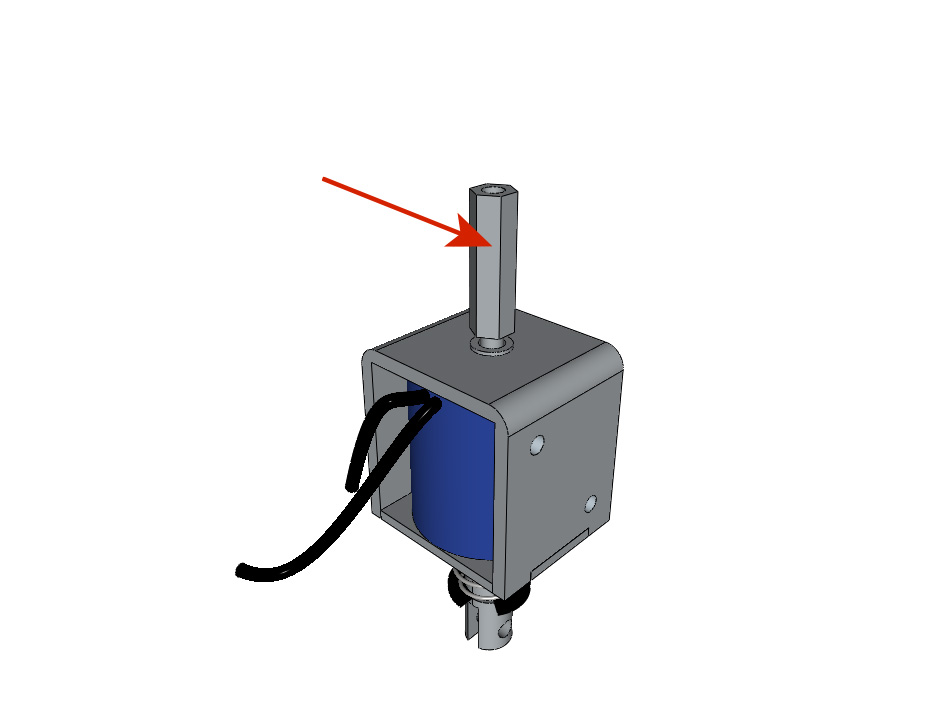
- Tighten the M3-12 screw with the needle punched out, allowing it to extend ± 6mm beyond the spacer.
Mounting the low truck (step 1)
equipment:
- Pre-assembled electromagnet assembly (see Preparing the electromagnet)
- 3D printed part : BOTTOM_trolley
- ** 3D printed parts ** : ELECTRO_MAGNET_housing
- ** 3D printed parts ** : ELECTRO_MAGNET_guide
- ** 3D printed parts ** : 3 X IGUS_housing
- 2 screw M3-8
- 3 IGUS
- 6 screws M3-12
- 10 M3 NYL nuts
- 2 M3-18 screw
- 2 M3-20 screw
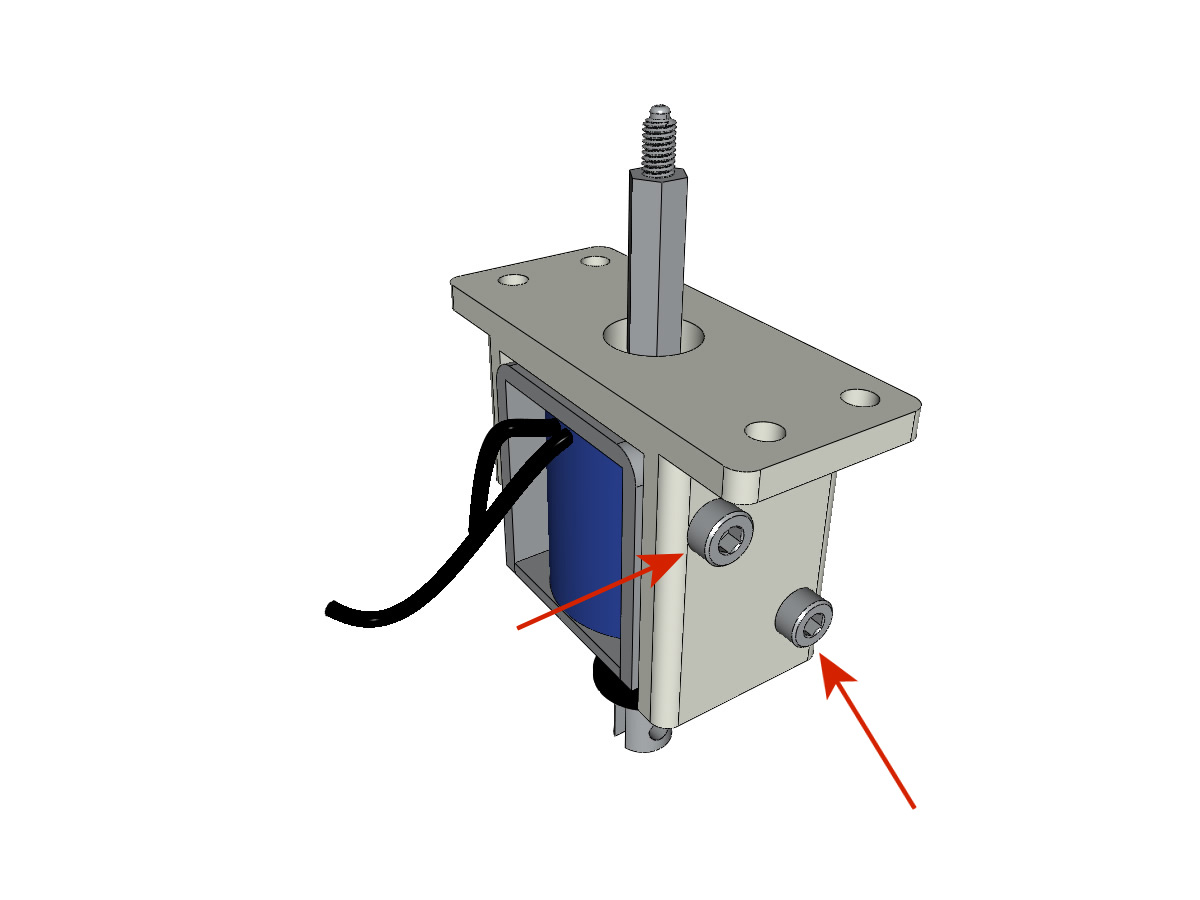
- Fix the electromagnet on its support with the 2 screws M3-8.
Attention
Observe the exit side of the wires.
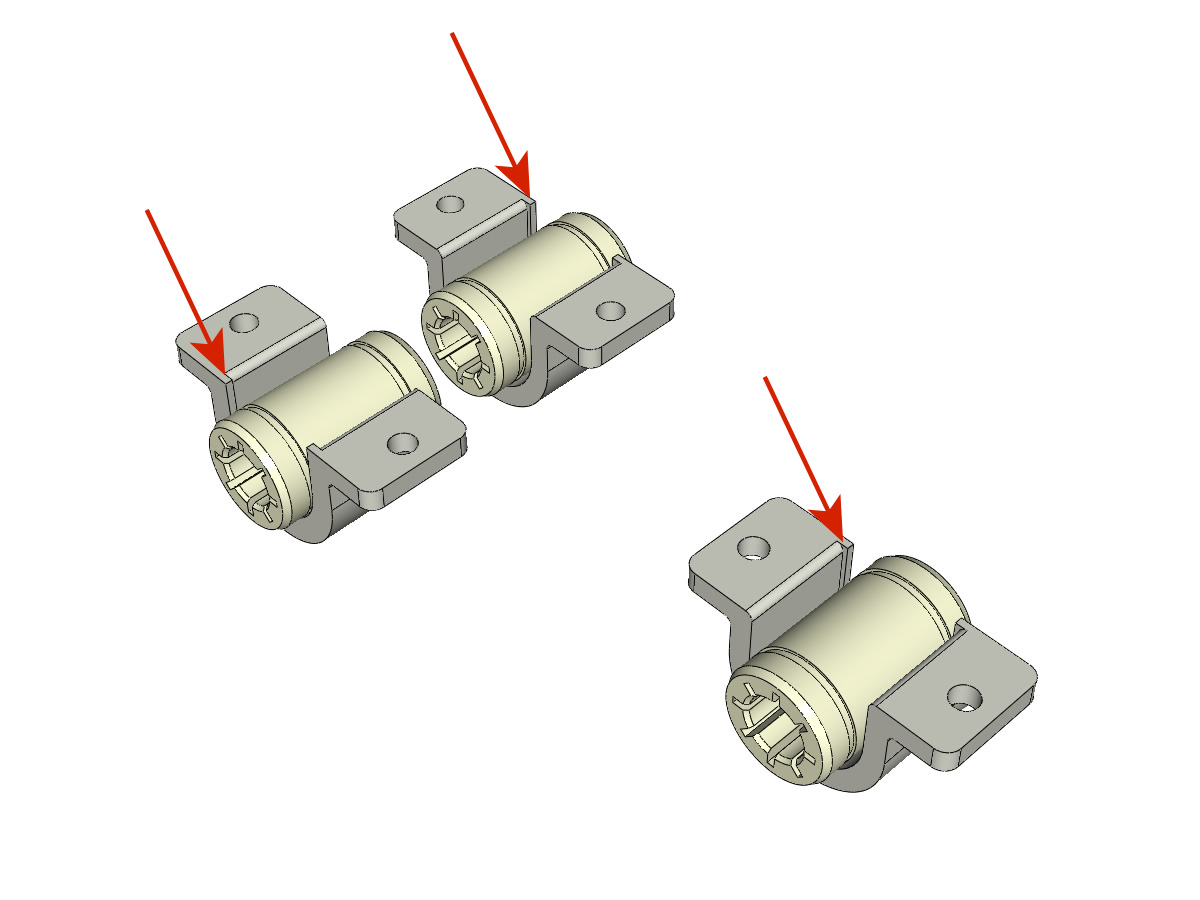
- Introduce the 3 IGUS in their housing (IGUS_housing).
Attention
Respect the grooving side.
- Assemble the 3 slots + IGUS + BOTTOM_trolley with the 6 screws M3-12 and the 6 nuts M3 NYL.
Attention
Do not tighten the screws thoroughly. They will be tightened when the carriage is in place on its guide rails.
- Assemble the electromagnet (previously mounted in its housing) under the BOTTOM_trolley and the ELECTRO_MAGNET_guide with two M3-18 screws and two M3 NYL nuts.
Attention
Depending on the quality of the print, it may be necessary to file the spacer housing.
- Screw the two M3-20 screws (which will hold the strap) and 2 M3 NYL nuts with the screw head underneath.
- Screw the two M3-20 screws (which will hold the strap) and 2 M3 NYL nuts with the screw head underneath.
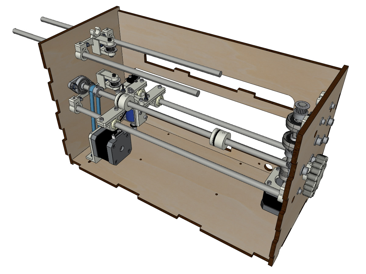
Mounting the low truck (step 2)
equipment:
- 2 linear shaft Ø8mm, length: 330mm
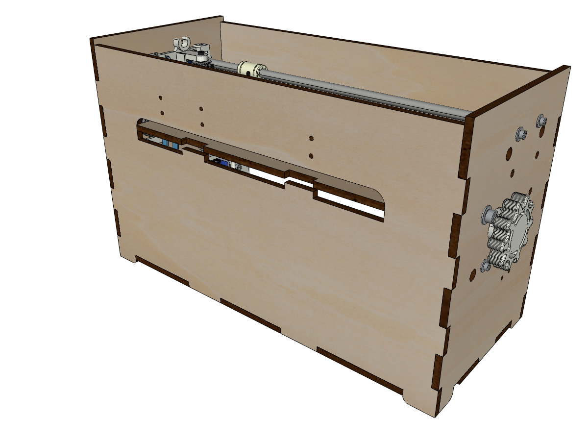
Note
We did not represent the facade for readability reasons.
- Thread the bars halfway through the outside of the crate.
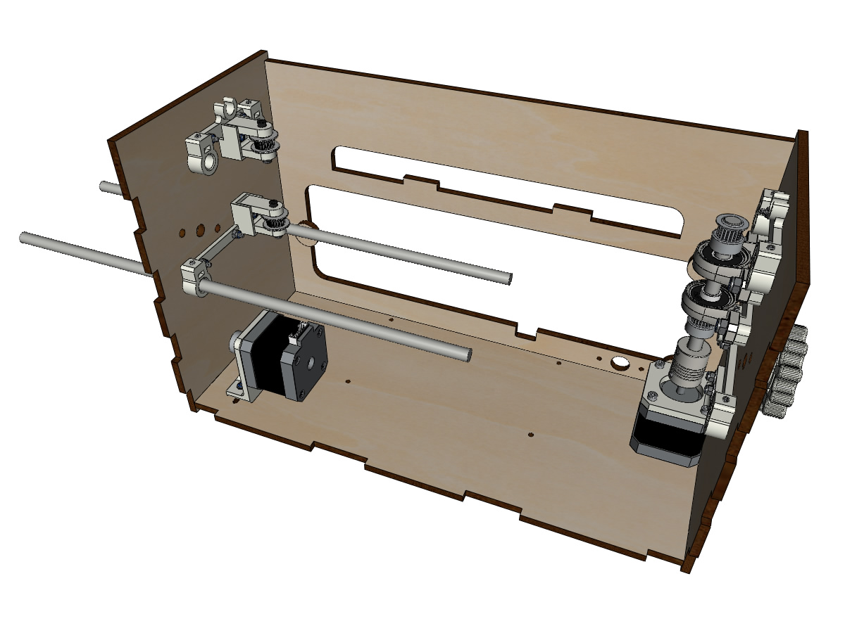
- Thread the switch and its support on the Ø8mm bar on the back side.
Note
The screw on the switch bracket will be tightened later during adjustment.
- Thread the trolley down over the smooth bars.
- Finish putting on the bars (the bars must not protrude into the wood of the box).
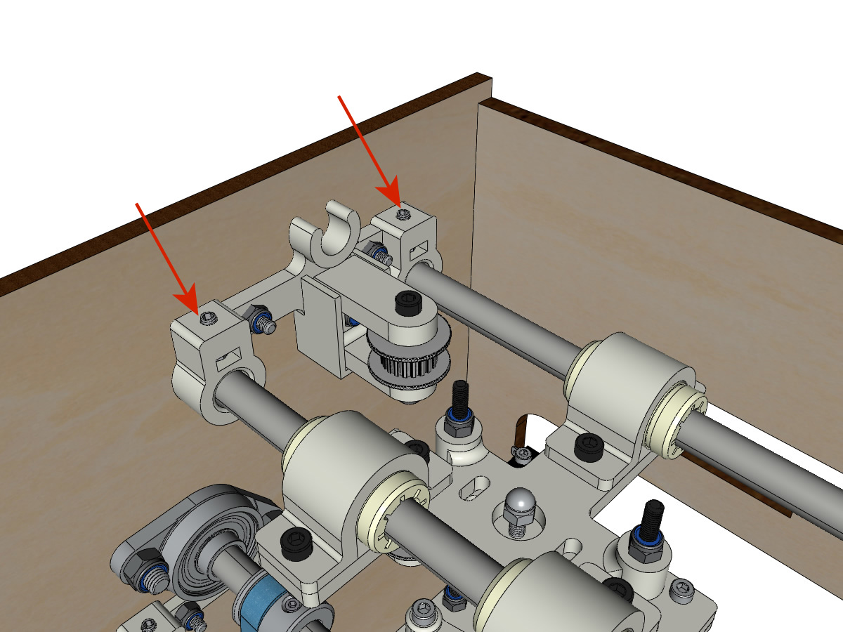
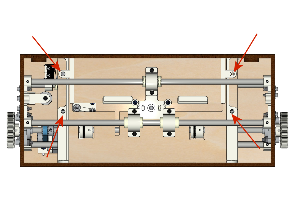
- Tighten the 4 axle holder screws on the body (2 on the left side and 2 on the right side) and the 4 grub screws on the axle brackets so that the pins do not slide into their seats.
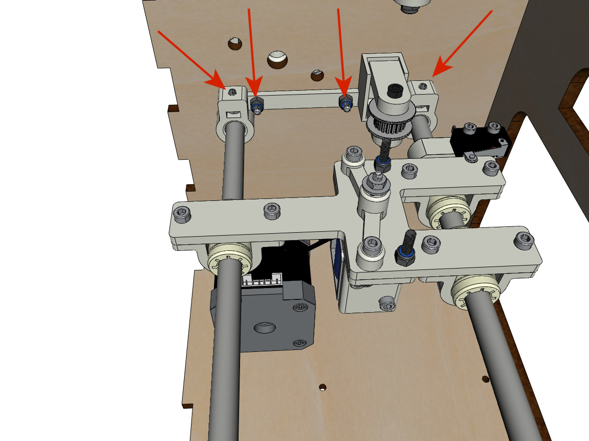
- Tighten the 6 screws of IGUS_housing little by little, making sure that the carriage slides well on the axes.
Mounting the vertical axis (step 1)
equipment:
- ** 3D printed parts ** : XMOTOR_support
- 1 Nema 17 motor
- 4 screw M3-8
- 2 screws M3-16
- 2 M3 NYL nuts
- 4 wide M3 washers
- Screw the motor on its support leaving a little play and respecting the position of the connector.
Note
The gap will then allow to align the motor shaft with the vertical axis.
- Visser l’ensemble moteur/support sur la caisse avec les 2 vis M3-16 en laissant du jeu.
Mounting the vertical axis (step 2)
equipment:
- ** 3D printed parts ** : 2 X KP08_support
- 2 KP08
- 4 vis M5-25
- 4 rondelles M5
- 4 M5 NYL nuts
Note
Before attaching the KP08, make sure the bearings are aligned in their housing. They may be delivered a little misaligned. In this case, insert a Ø 8mm bar and manually actuate it to straighten them.
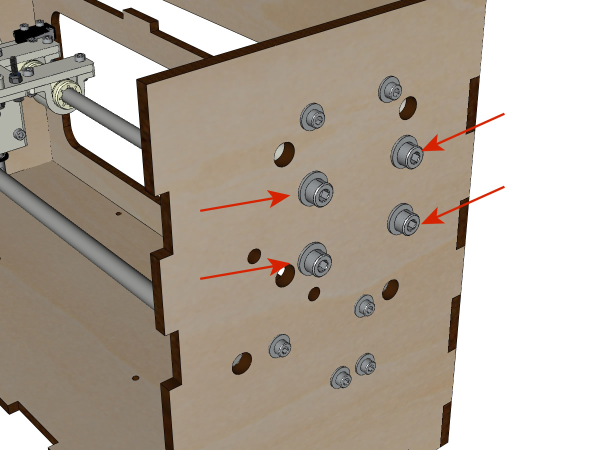
- Visser les KP08_support et les KP08 sur la caisse en laissant un peu de jeu avec les vis M5-25, les rondelles M5 et les écrous M5 NYL.
- Observe the position of the KP08 clamping rings.
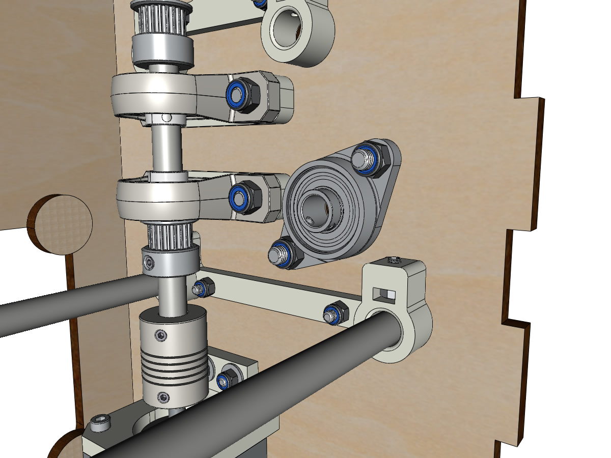
Mounting the vertical axis (step 3)
equipment:
- 1 linear shaft Ø 8mm, length : 100mm
- 1 5*8mm Coupler
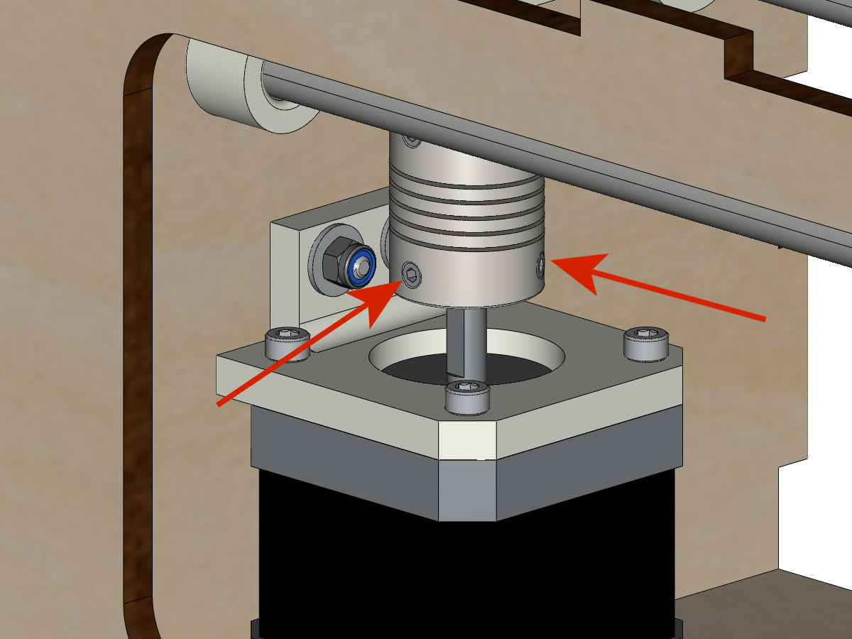
- Thread the coupler onto the motor shaft (Ø 5mm hole at the bottom).
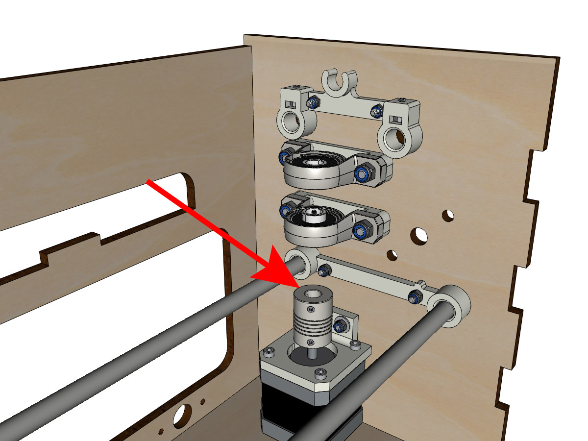
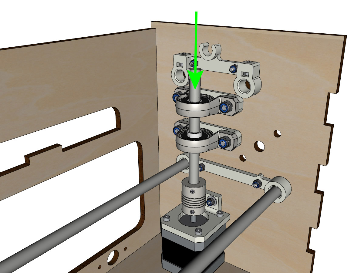
- Thread the 100mm linear shaft from the top through the KP08 and into the coupler.
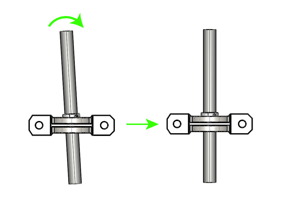
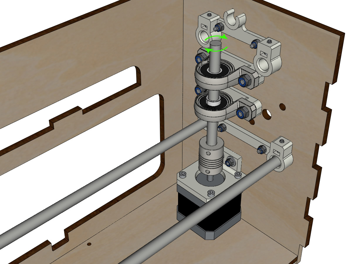
- Rotate the linear shaft by hand to ensure that all elements are aligned and that the spindle continues to rotate freely.
- The holes of the motor support are oblong and allow to align the motor with the vertical axis in the 2 dimensions.
- Screw the first 2 screws of the motor on its support.
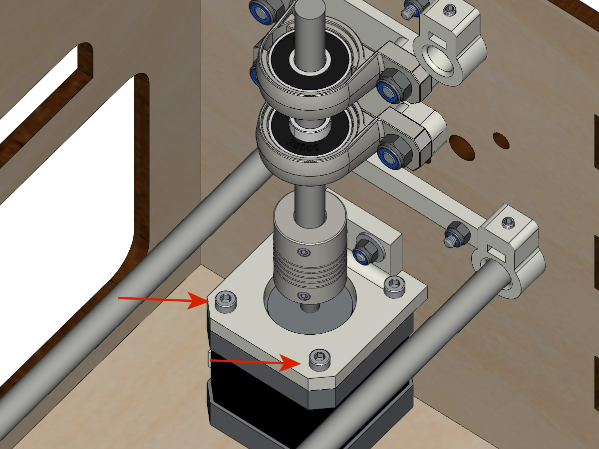
- Slowly tighten the KP08 screws by turning the shaft by hand.
- Screw the motor support screws onto the body slowly by turning the shaft by hand. ** ADD PICTURE **
- Remove the pin and finish screwing the last 2 screws of the motor on its support, then the support on the body.
Mount the vertical axis (step 4)
equipment:
- 2 pulleys GT2 20 teeth bore 8mm
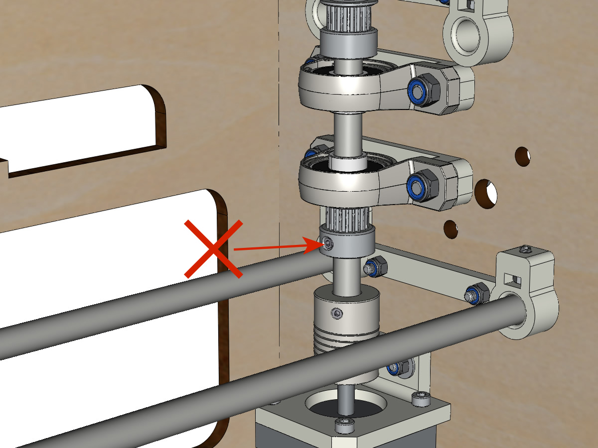
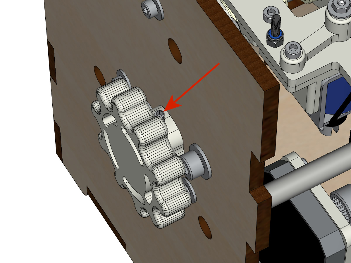
- Screw the 2 screws at the bottom of the coupler onto the motor shaft, making sure that one of the screws is in front of the flat part of the motor shaft and that the bottom of the coupler is not resting on the motor.
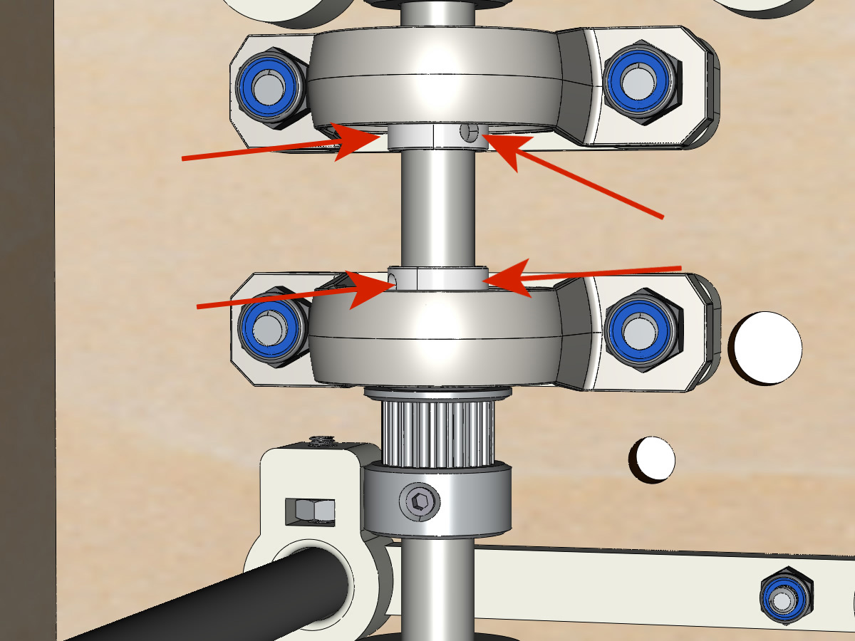
- Thread the 100mm axle into the KP08, the pulleys (respecting their positions) and the coupler.
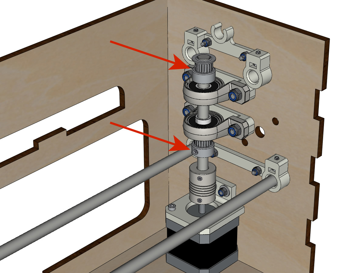
- Screw the 2 screws at the top of the coupler onto the vertical axis.
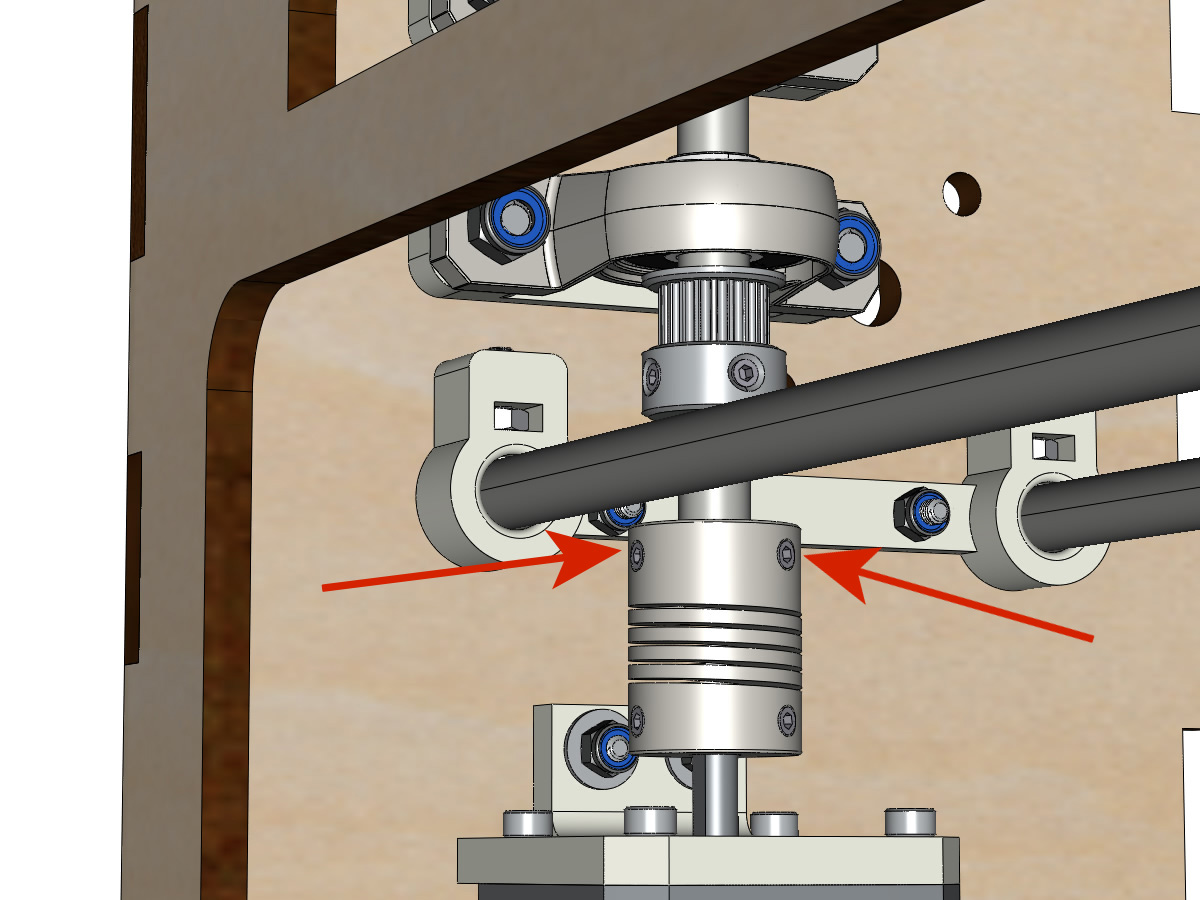
- Leave the pulleys free without screwing them onto the axle. They will be screwed when the belt is in place.
- Screw the screws of the KP08 clamping rings (2 screws per ring).
- Make sure that the axle rotates easily and that the motor does not oscillate. If necessary, loosen the motor and support screws on the body to give them play and re-align.
Mounting the low carriage belt
equipment:
- 1 belt GT2 length ± 620mm
- 2 necklaces
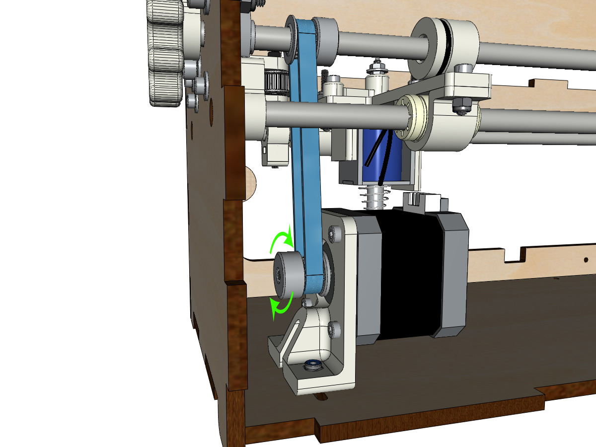
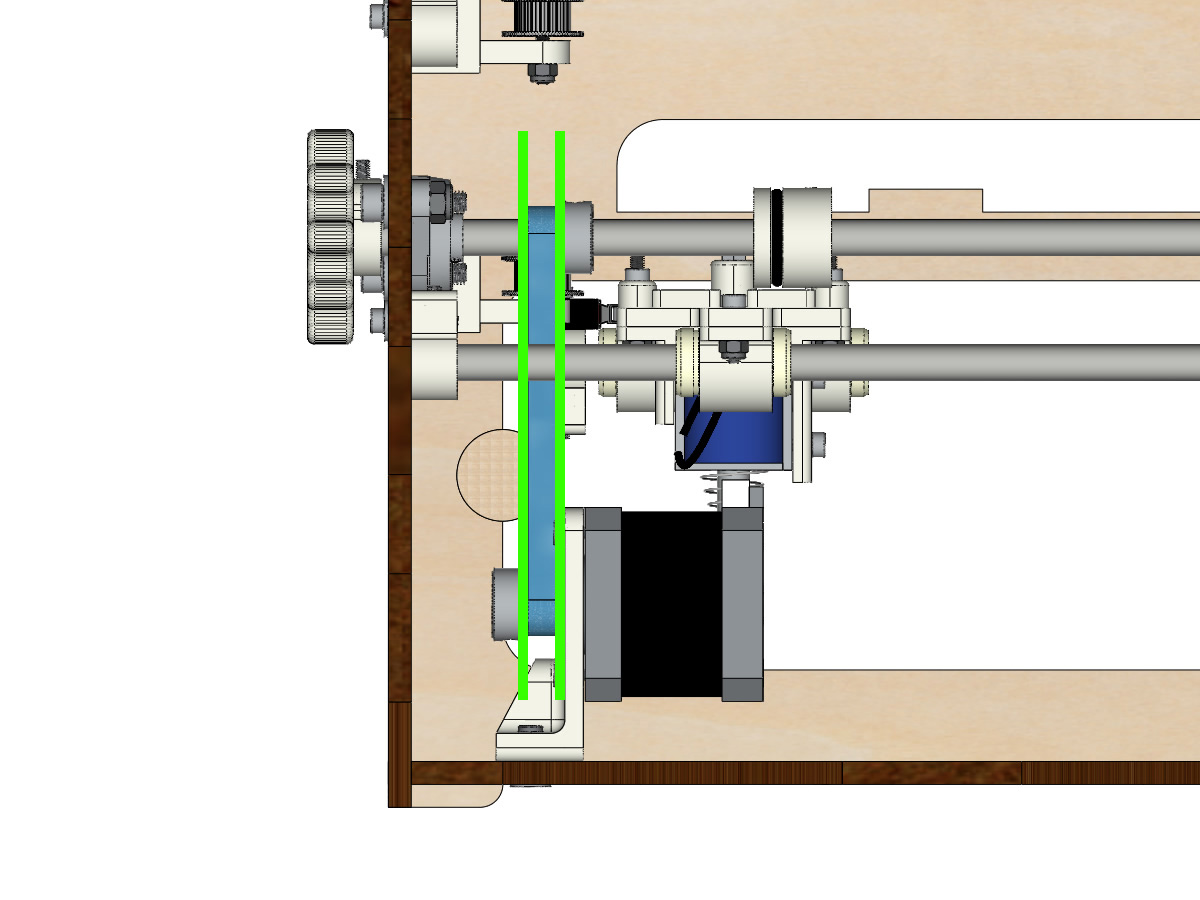
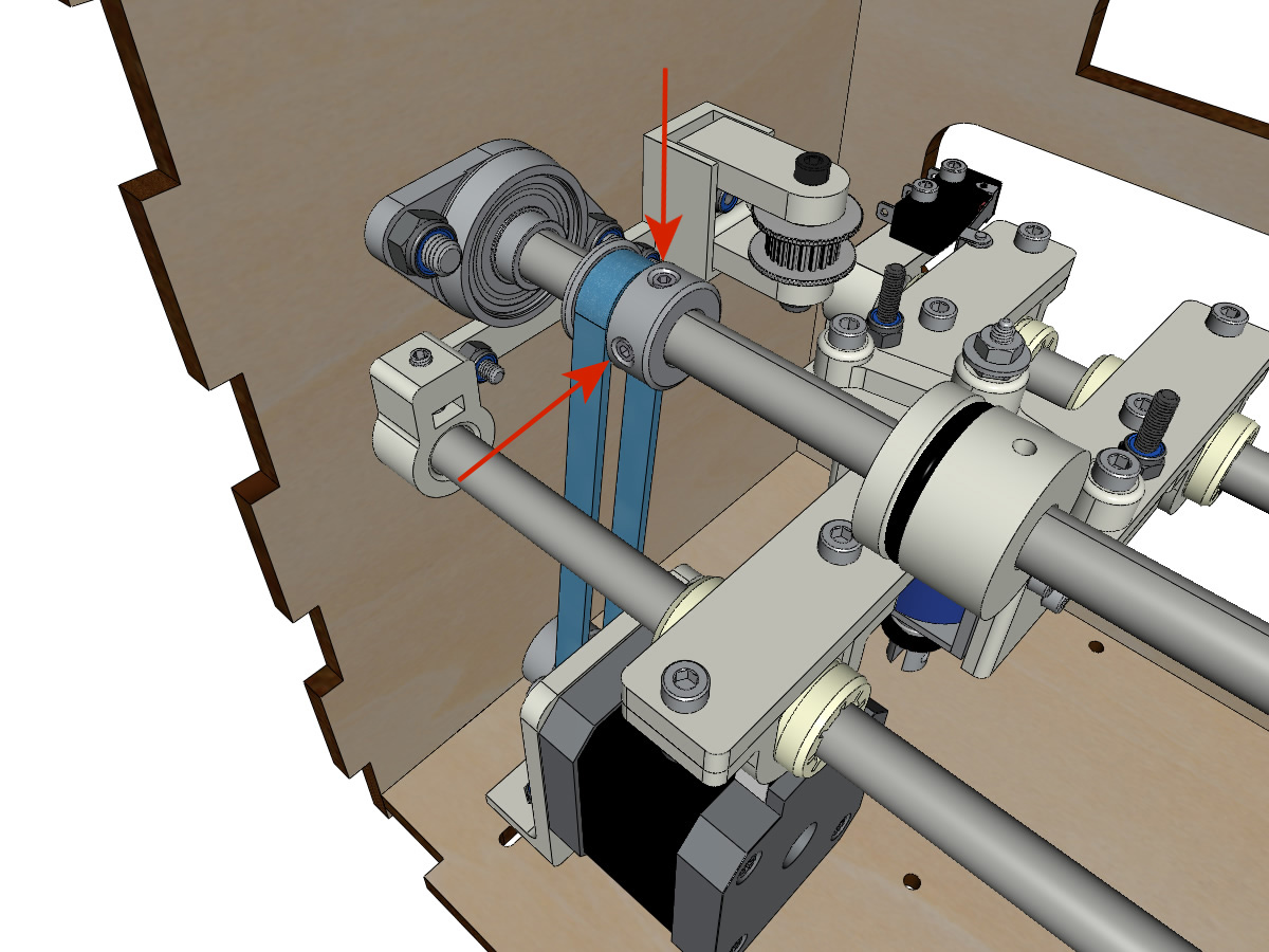
- Using a collar, attach the strap around the carriage screw with the teeth facing out. ** ADD PICTURE **
- Pass the belt in the free pulley then the pulley of the vertical axis.
- Tension the belt while holding the carriage and secure the second end of the belt to its screw with a collar. ** ADD PICTURE **
- Finish stretching the belt with the screw on the outside of the body. ** ADD PICTURE **
Note
For now, do not tighten the pulley bolts on the axle.
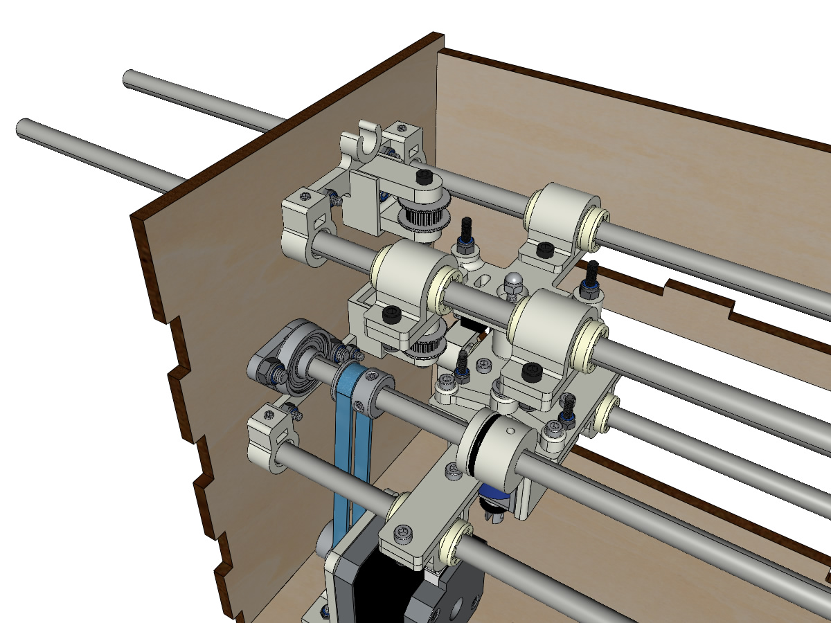
Mounting the Y axis (step 1)
equipment:
- ** Piece (s) printed in 3D **: 2 x ROLL_joint
- 1 tap M3
- 2 O-rings
- 2 vis M3-6 sans tête bout pointeau
- 2 KFL8
- 4 screws M5-18
- 4 M5 NYL nuts
- 4 rondelles M5
- 1 GT2 20 teeth boron 8mm pulley
- 1 smooth bar Ø 8mm, length: 364mm
- 1 closed GT2 belt 200 or 220 mm (according to the Y motor support)
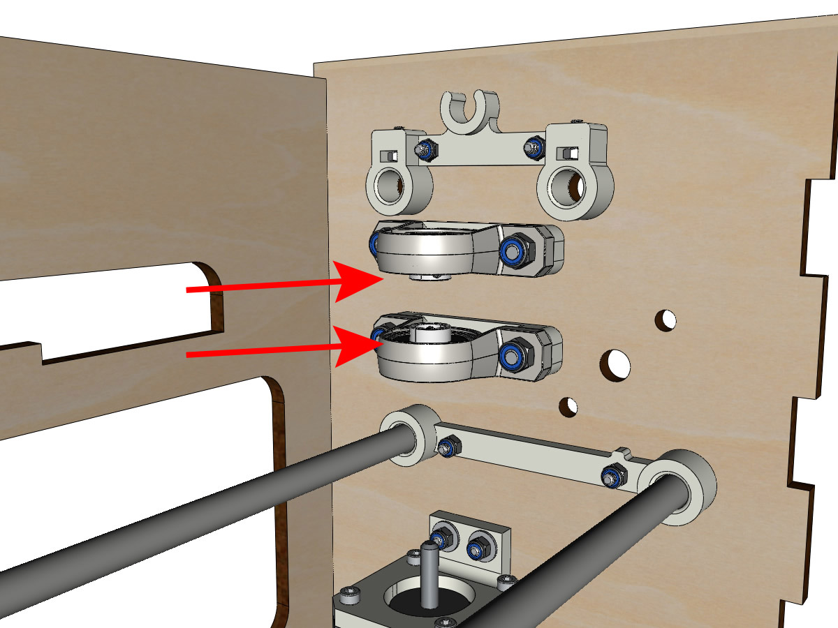
- Fix the KFL8 on the left side with 2 M5-18 screws, 2 M5 washers and 2 M5 NYL nuts.
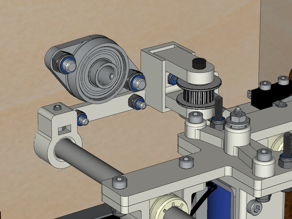
- Fix the KFL8 right on the body with the KFL8_support, 2 screws M5-18, 2 washers M5 and the 2 nuts M5 NYL.
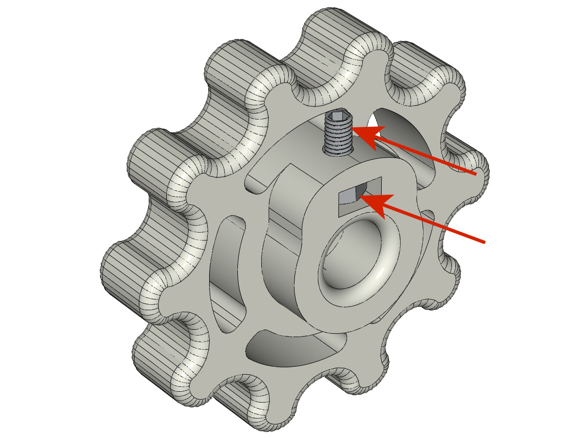
- Tape the 2 ROLL_joint.
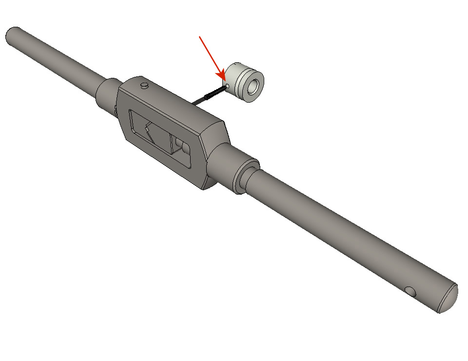
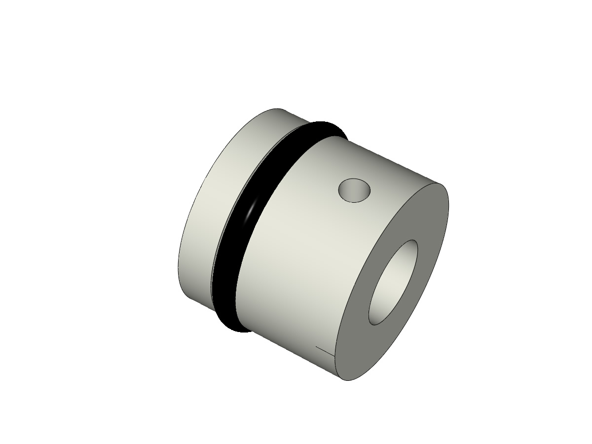
- Put the O-rings in the groove of the 2 ROLL_joint.
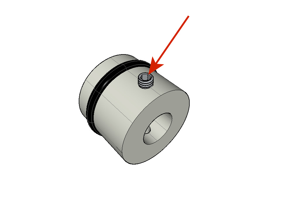
- Screw the M3-5 headless screws making sure they do not protrude into the hole.
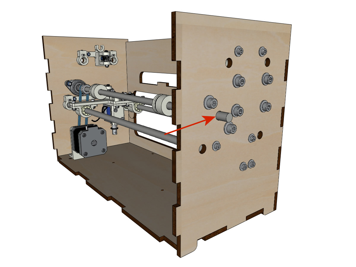
- Thread the smooth bar halfway through the left side through the body and the KFL8.
- In order, thread the GT2 20 tooth boron 8mm pulley, the closed belt and the 2 ROLL_joint (pay attention to the position of the O-ring). Put the belt closed on the pulley of motor Y and on the pulley of the axle.
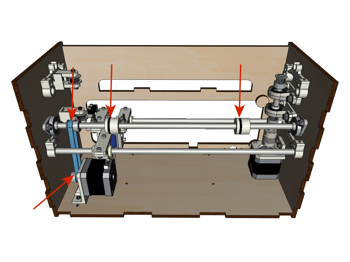
- Press the axle into the right KFL8 and cross it so that it protrudes ± 12mm from the body.
- Tighten the screws of the KFL8 rings.
Wheel assembly
equipment:
- ** Piece (s) printed in 3D **: 2 x SCROLL_wheel
- 2 screws M3-8 without head ** Michel, we put you M3-12 without head;) **
- 2 nuts M3
- Insert the M3 nuts into their housing and screw in the M3-8 headless screws.
- Fix the knobs on the axle by tightening the M3-8 screws without head.
Mounting the Y axis (step 2)
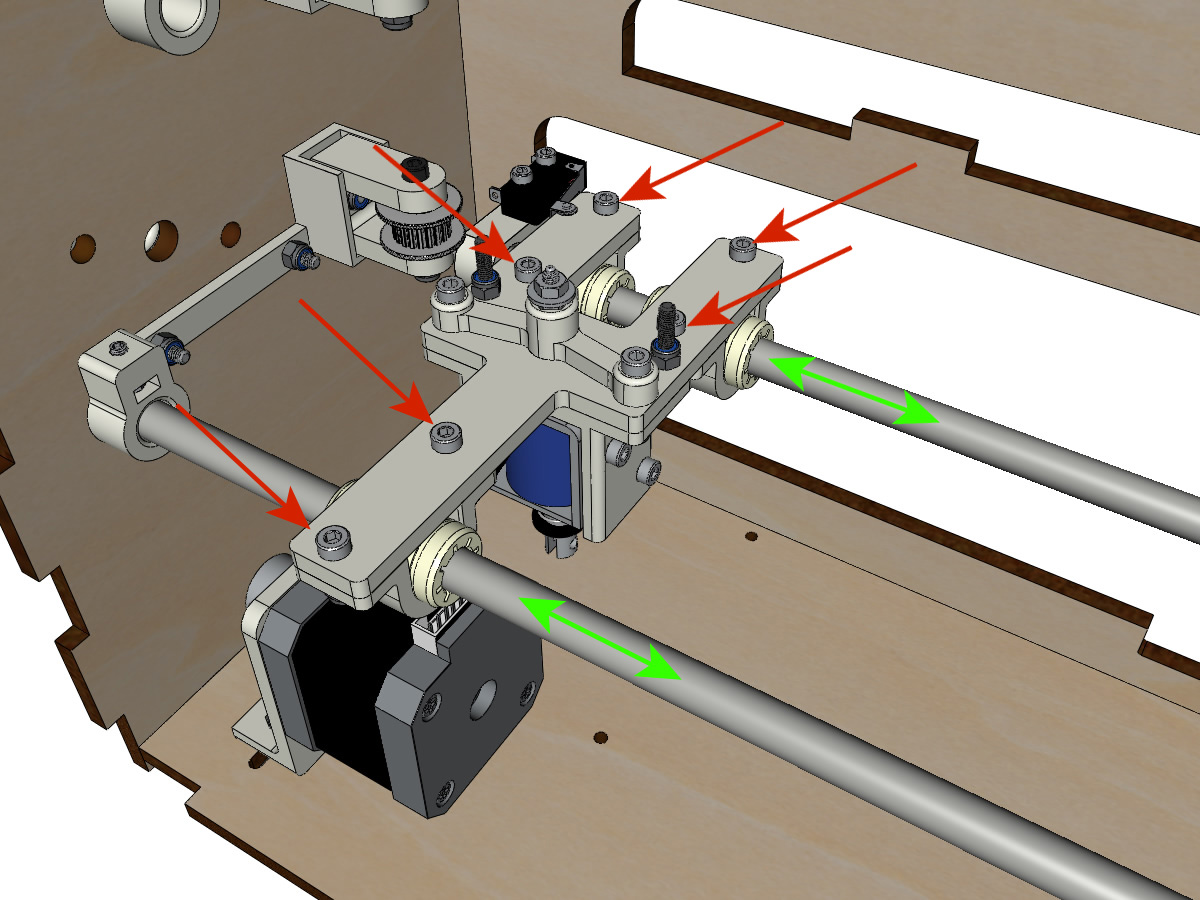
- Rotate the motor pulley by hand so that the pulley on the shaft aligns vertically with the motor pulley.
- Move the Y motor / support assembly along the oblong holes under the body to tension the closed belt and tighten the 2 screws.
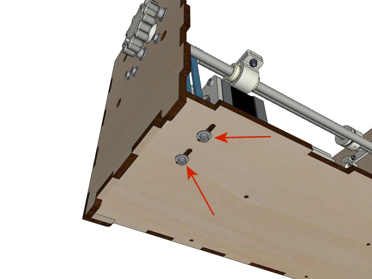
- Tighten the 2 screws of the pulley of the axle.
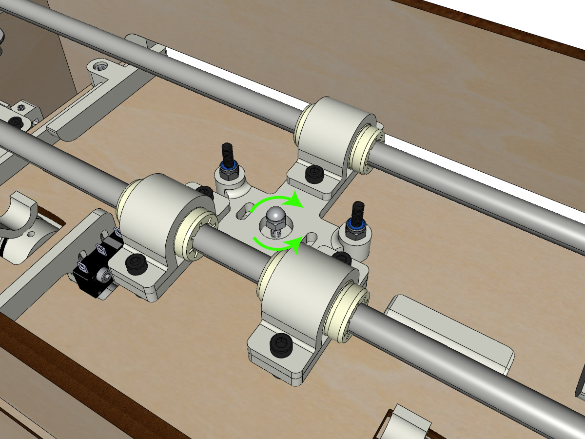
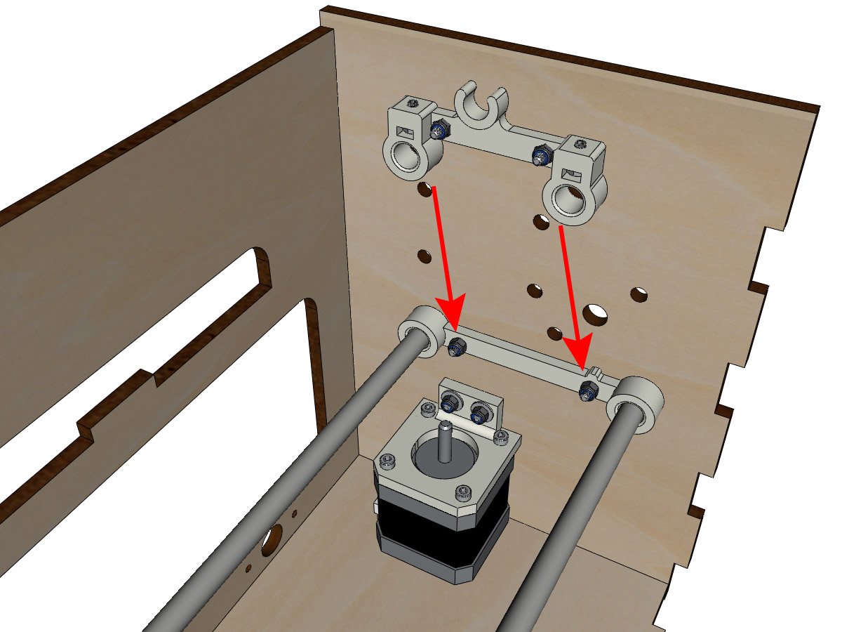
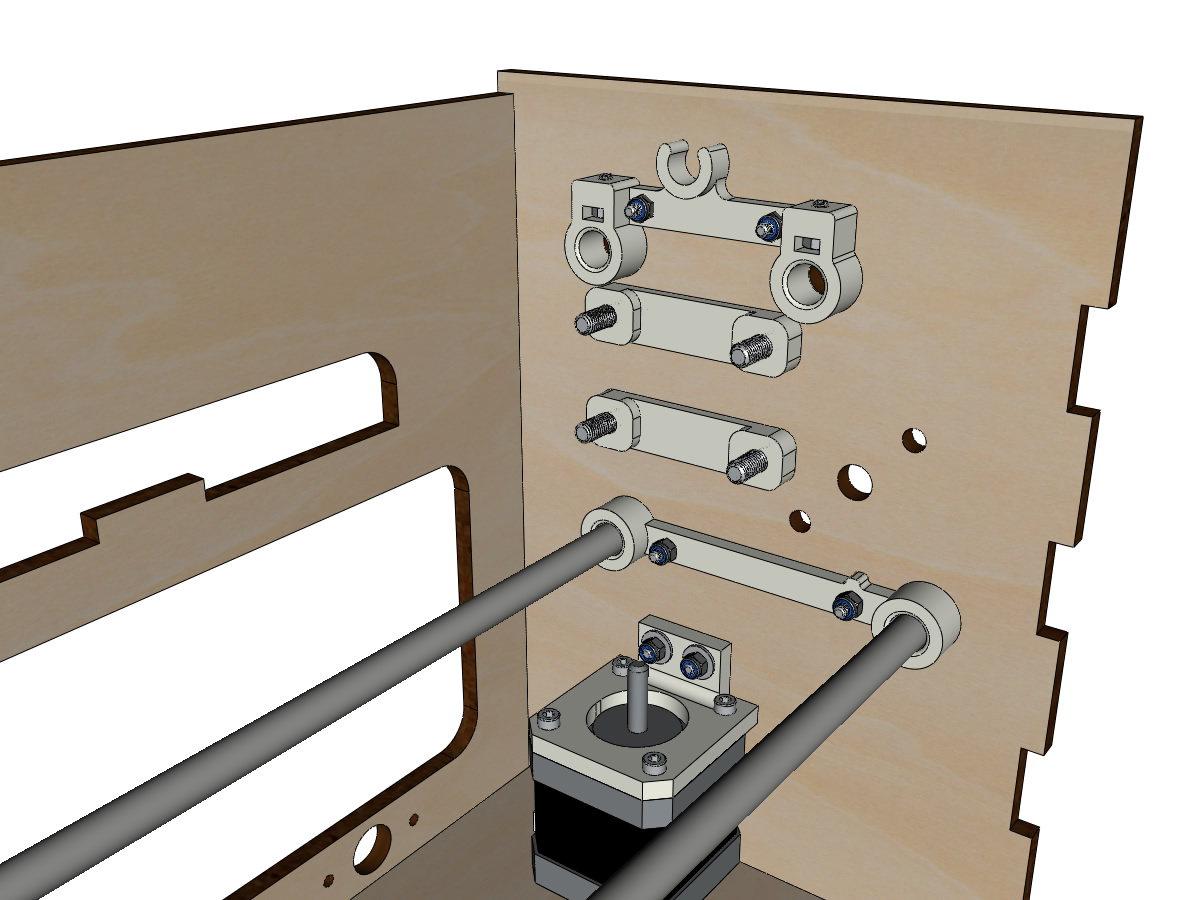
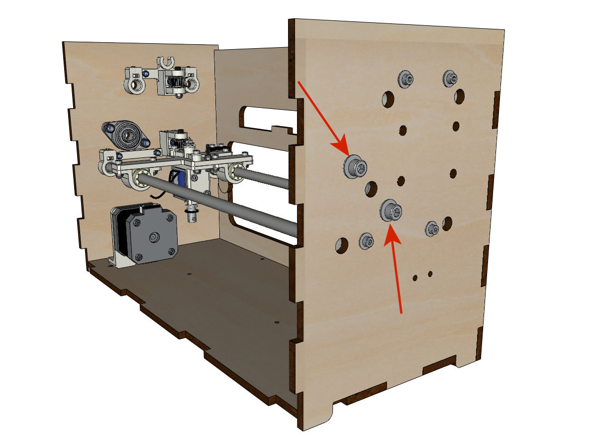
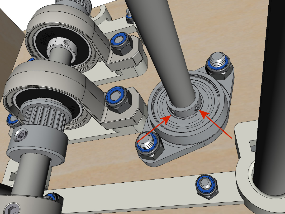
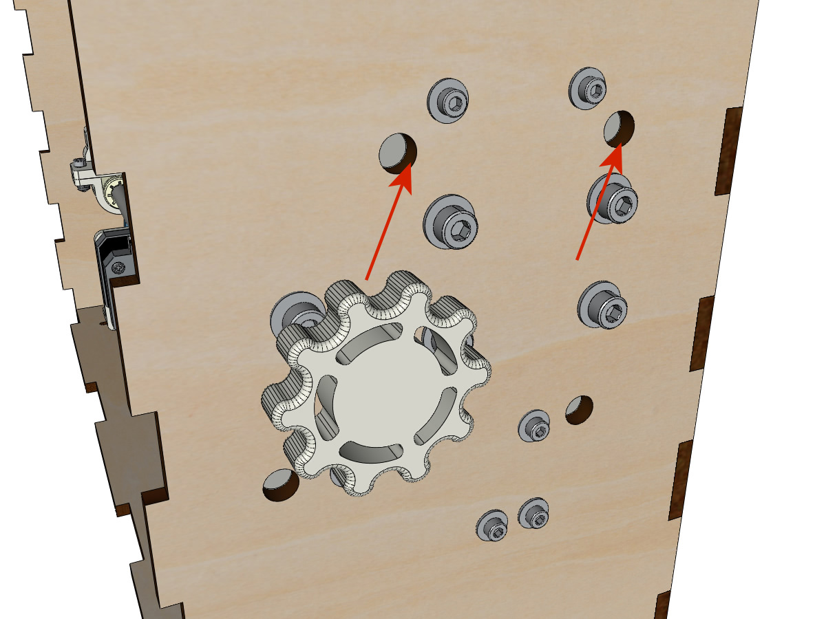
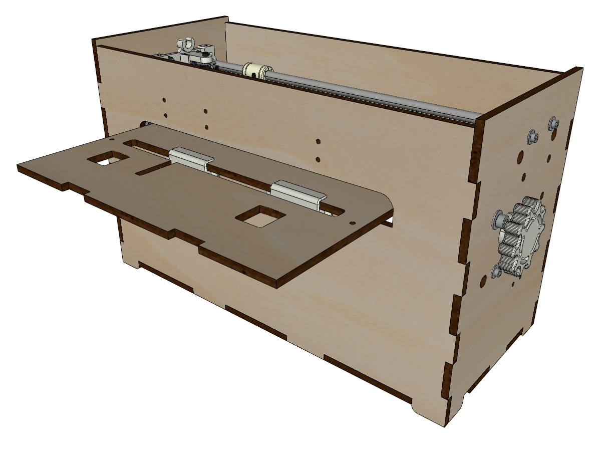
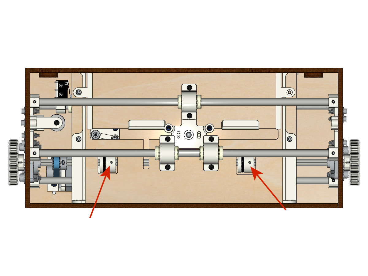
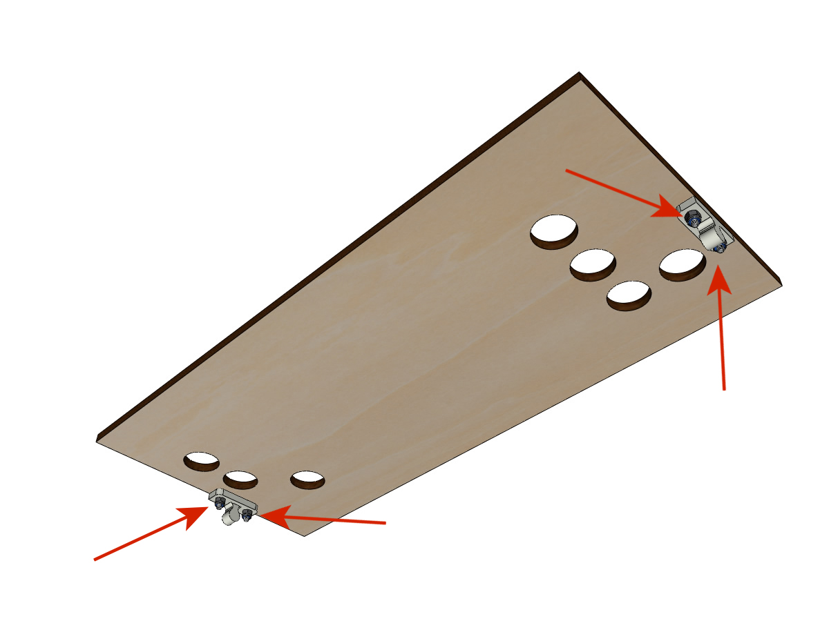
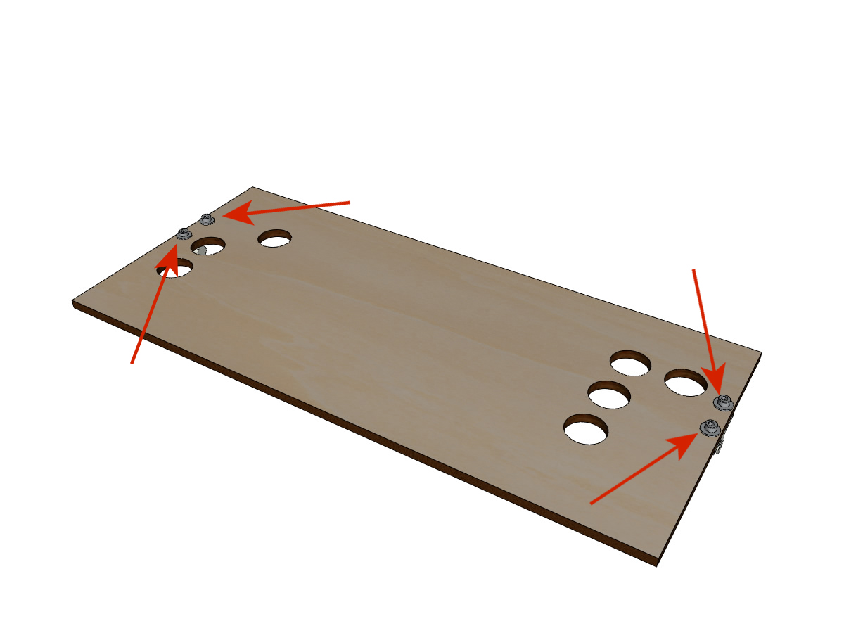
- Place the CP board (without gluing it) to align the ROLL_joint with the holes in the board. ** ADD PICTURE **
- When the ROLL_joint is in place, tighten the grub screws. ** ADD PICTURE **
- Remove the plywood plate.
Mounting the top cart (step 1)
equipment:
- Glue the thread of the cap nut and screw the M3-30 screw without head on the side ** WITHOUT ** borrows allen.
- Tape the FEMALE_shape 2/3 from the top.
- Tighten the M3-30 screw / blind nut assembly to allow it to exceed ± 0.5mm.
- Assemble the FEMALE_shape on the TOP_trolley with the M3-12 screws, the M3 washers and the NYL M3 nuts.
- Position the IGUS in the IGUS_housing respecting the side of the blocking and then screw on the carriage with the M3-12 and M3 NYL nuts.
- Fit the M3-20 screws and the M3 nuts.
Mounting the top cart (step 2)
equipment:
- 2 smooth bars Ø 8mm, length: 330mm
- Thread the bars halfway through the outside of the crate.
- Thread the trolley down over the smooth bars.
- Finish putting on the bars.
Note
The edge of the wood should remain visible.
- Tighten the axle holder screws on the body on the left and right.

- Screw the grub screws of the axle supports on the left and right.
Laying the trolley strap up
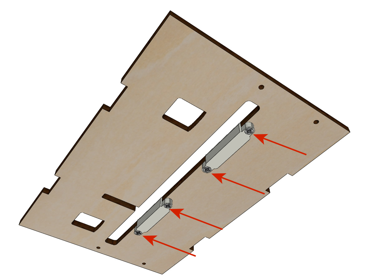
Mounting the lifter on the plate
equipment:
- PAPER_support (laser cut 5mm plywood).
- ** Piece (s) printed in 3D **: 2 PAPER_raiser
- 4 wood screws 3-10 countersunk head ** Michel, we did not have any anymore; (E **
- Screw the 2 PAPER_raiser onto the plate from underneath with the wood screws.
Bonding of the paper plate
equipment:
- PAPER_support (laser cut 5mm plywood).
- ** Piece (s) printed in 3D **: 2 PAPER_raiser
- Glue the notches that will be in contact. Insert the plate from the front and hold it firmly with tape during the drying time.
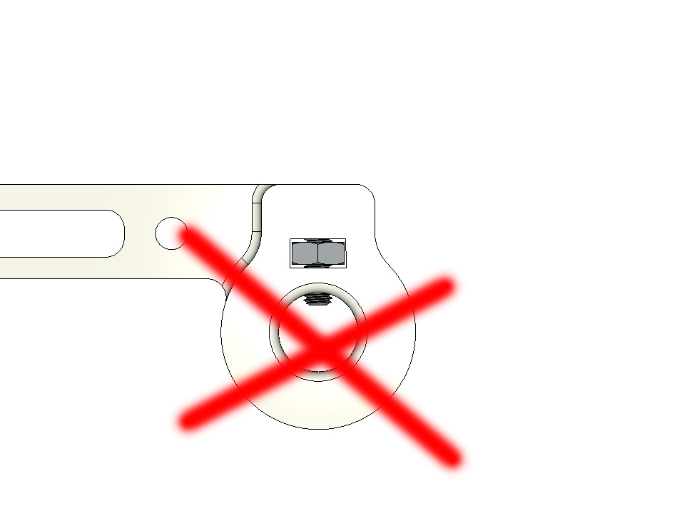
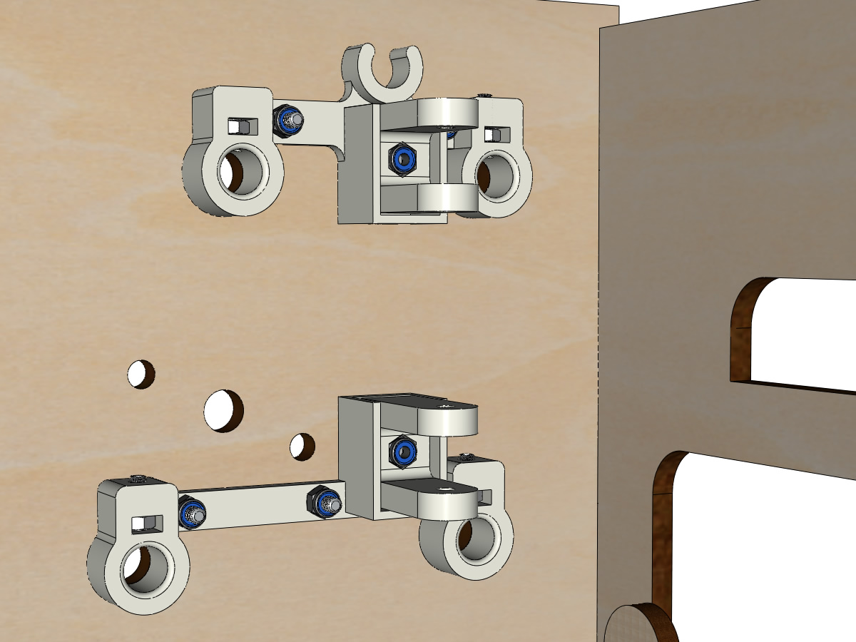
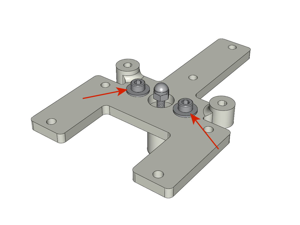
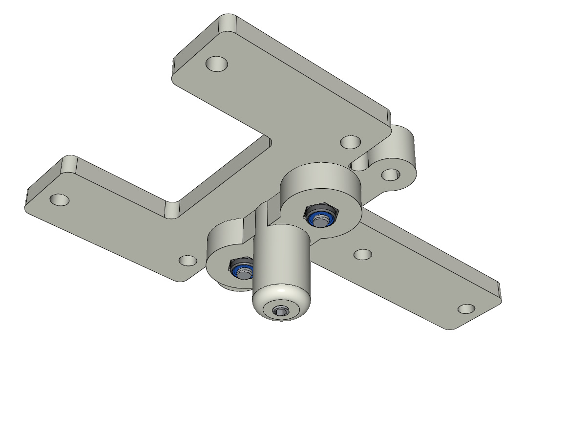
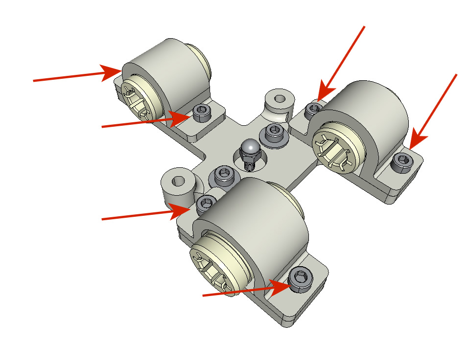
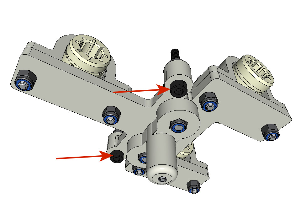
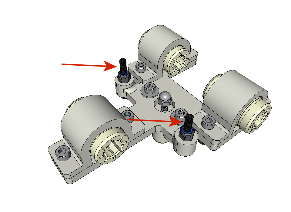
Assembling the paper guides on the plate
equipment:
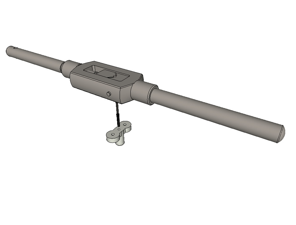
Note
For clarity, we have isolated the concerned part.
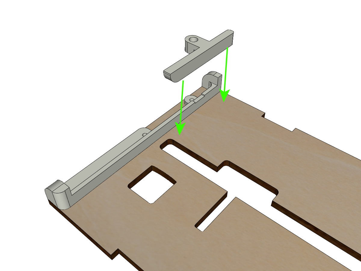
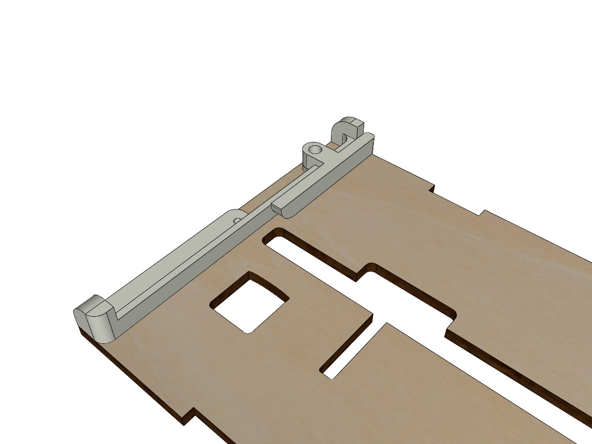
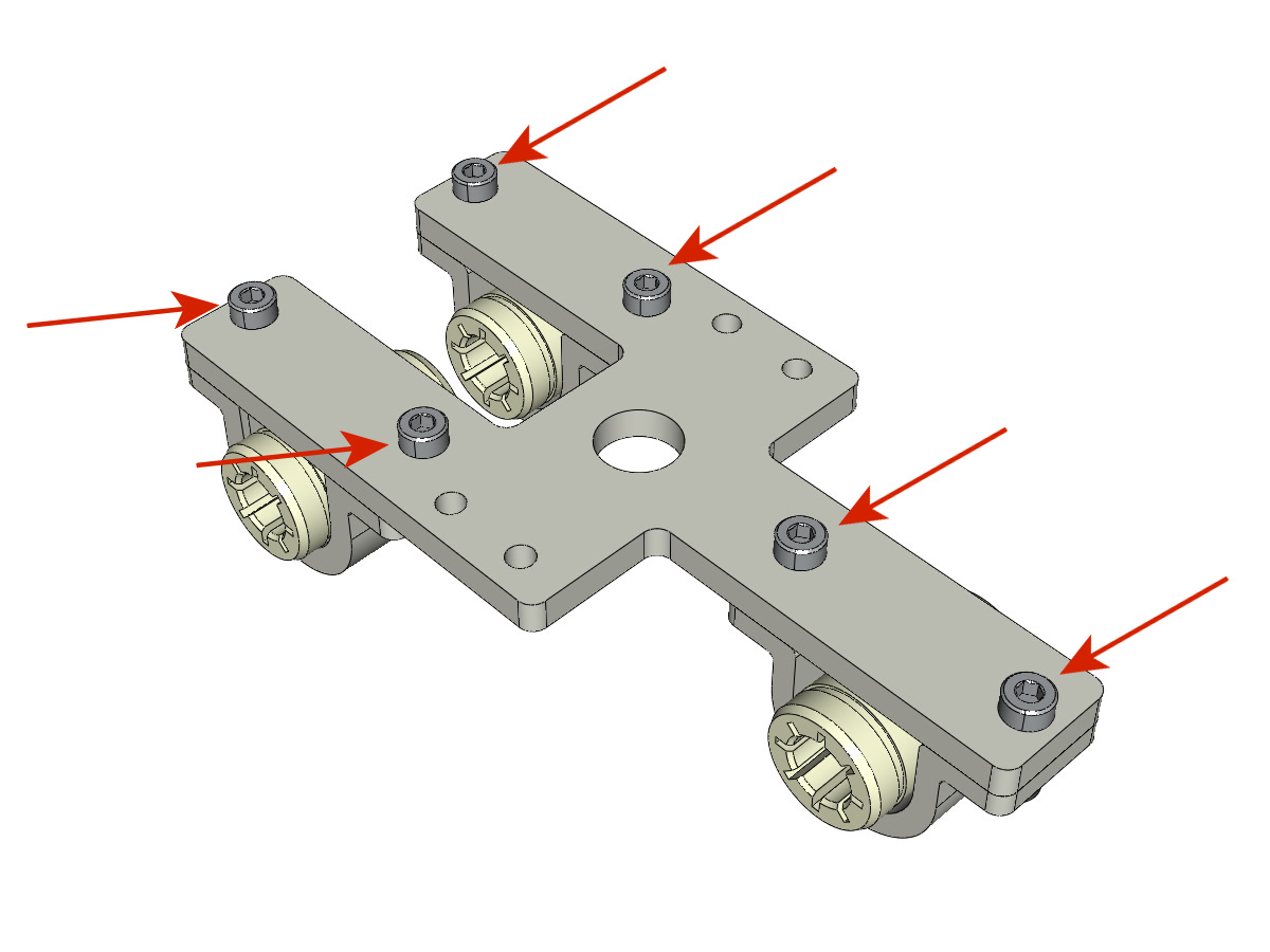
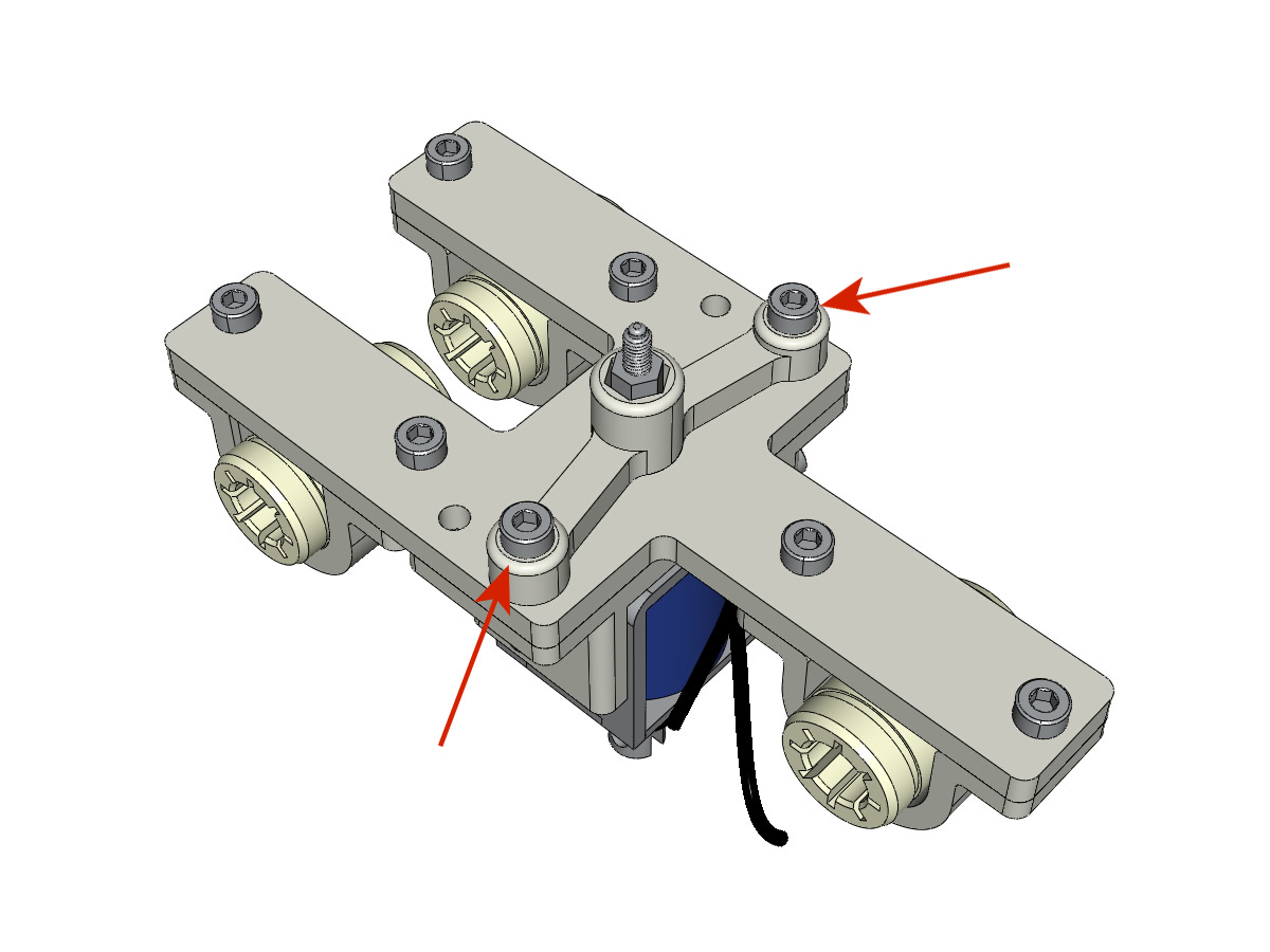
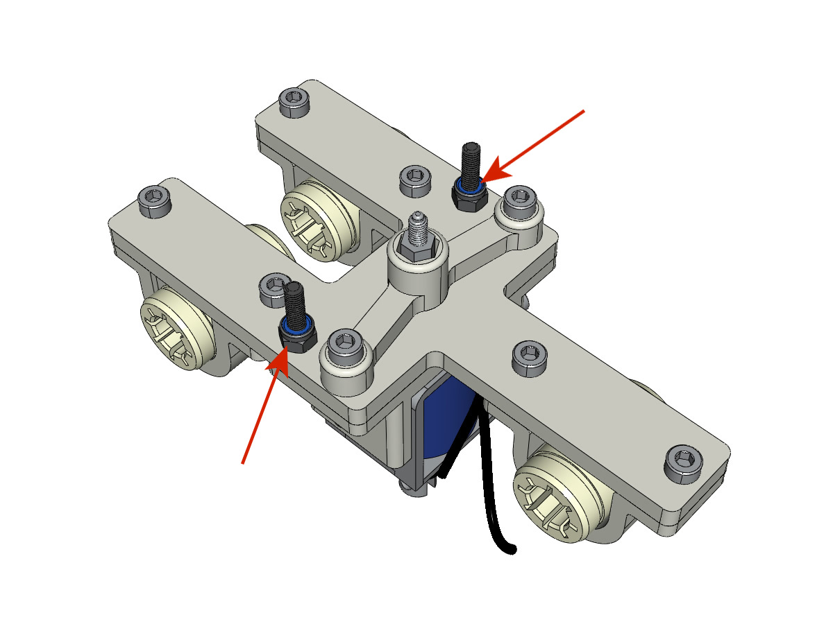
- Assemble the paper guides on the plate with the M3-16 screws and M3 NYL nuts.
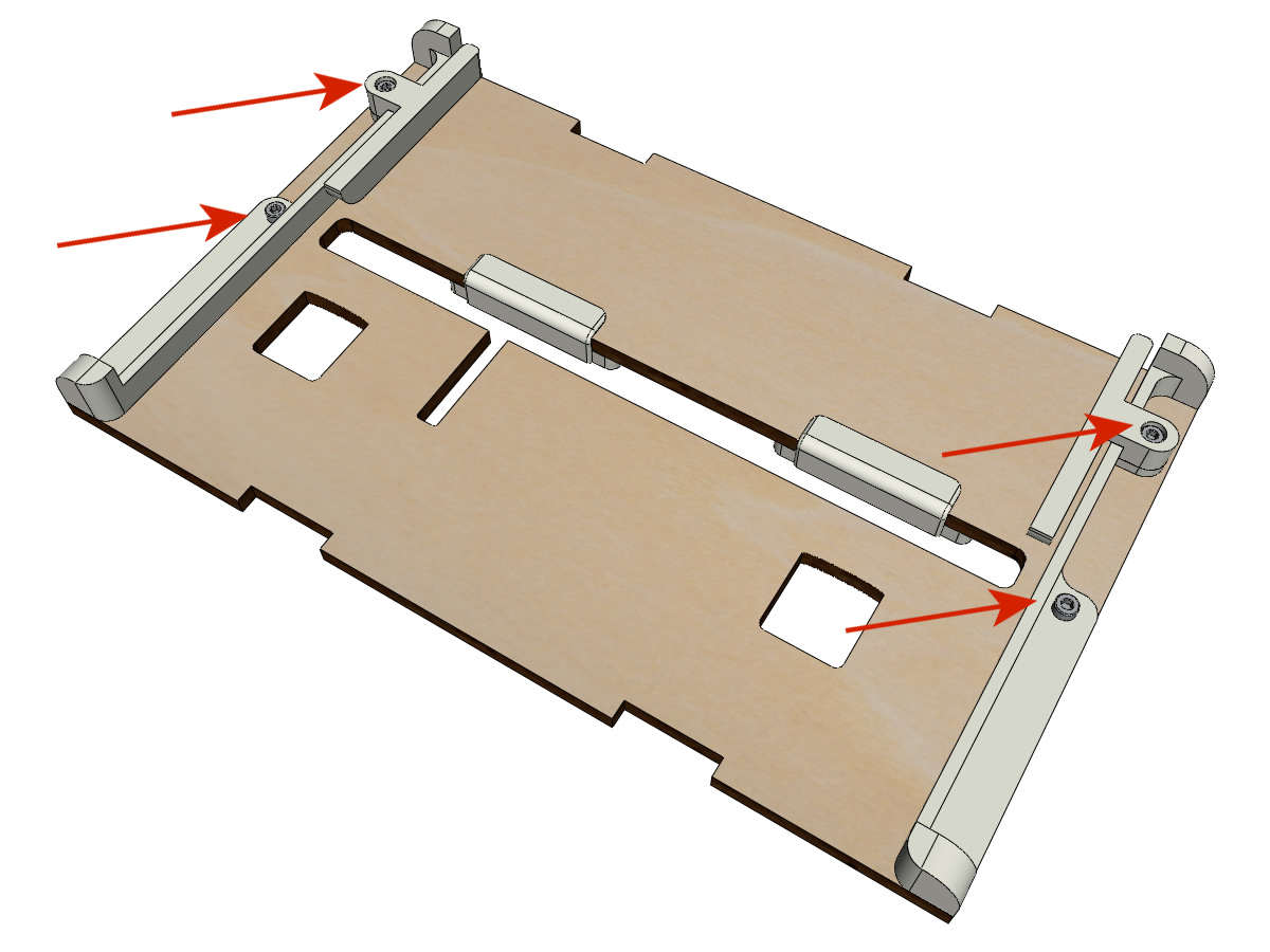
- You must get a view from above like this:
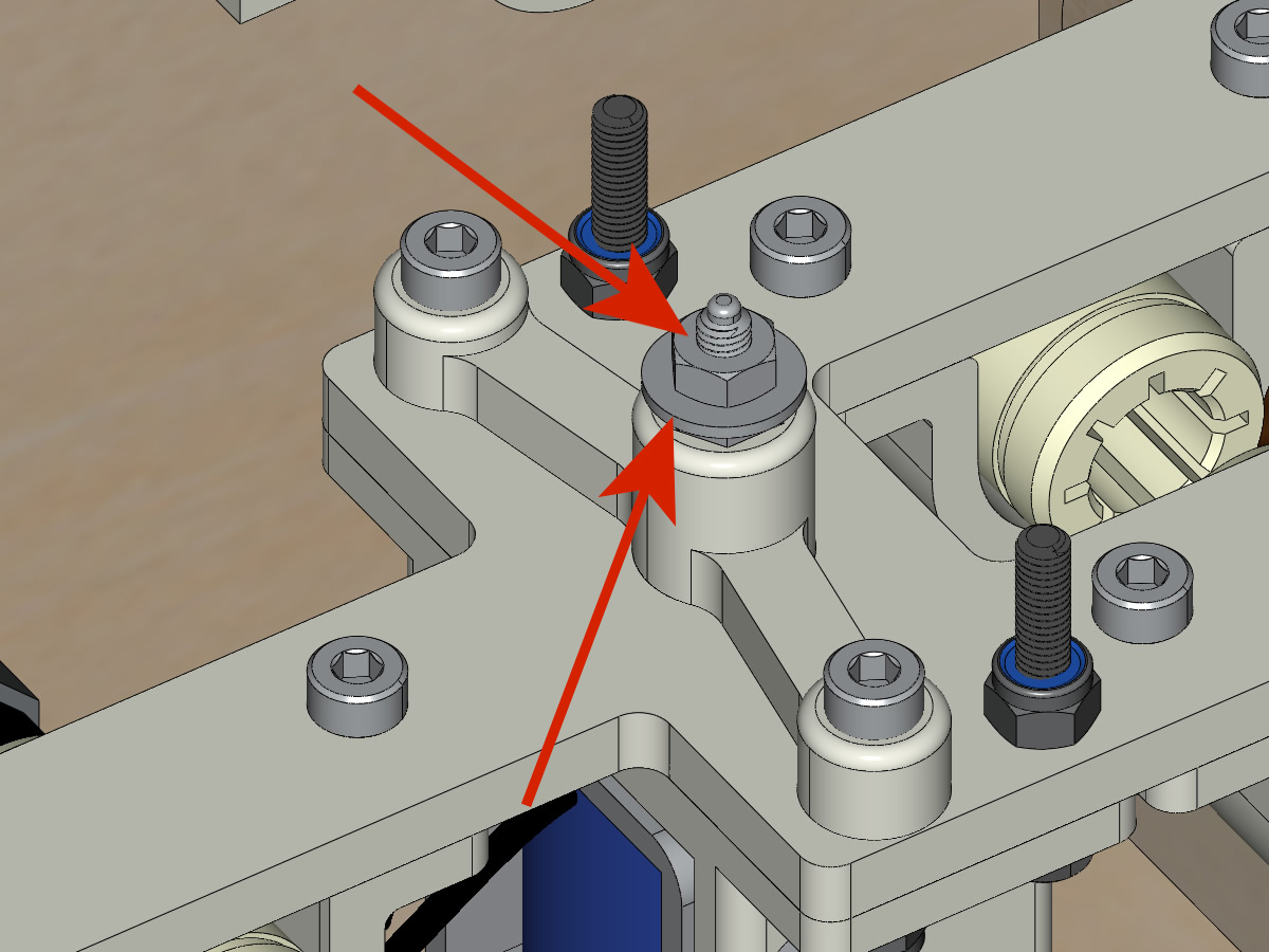
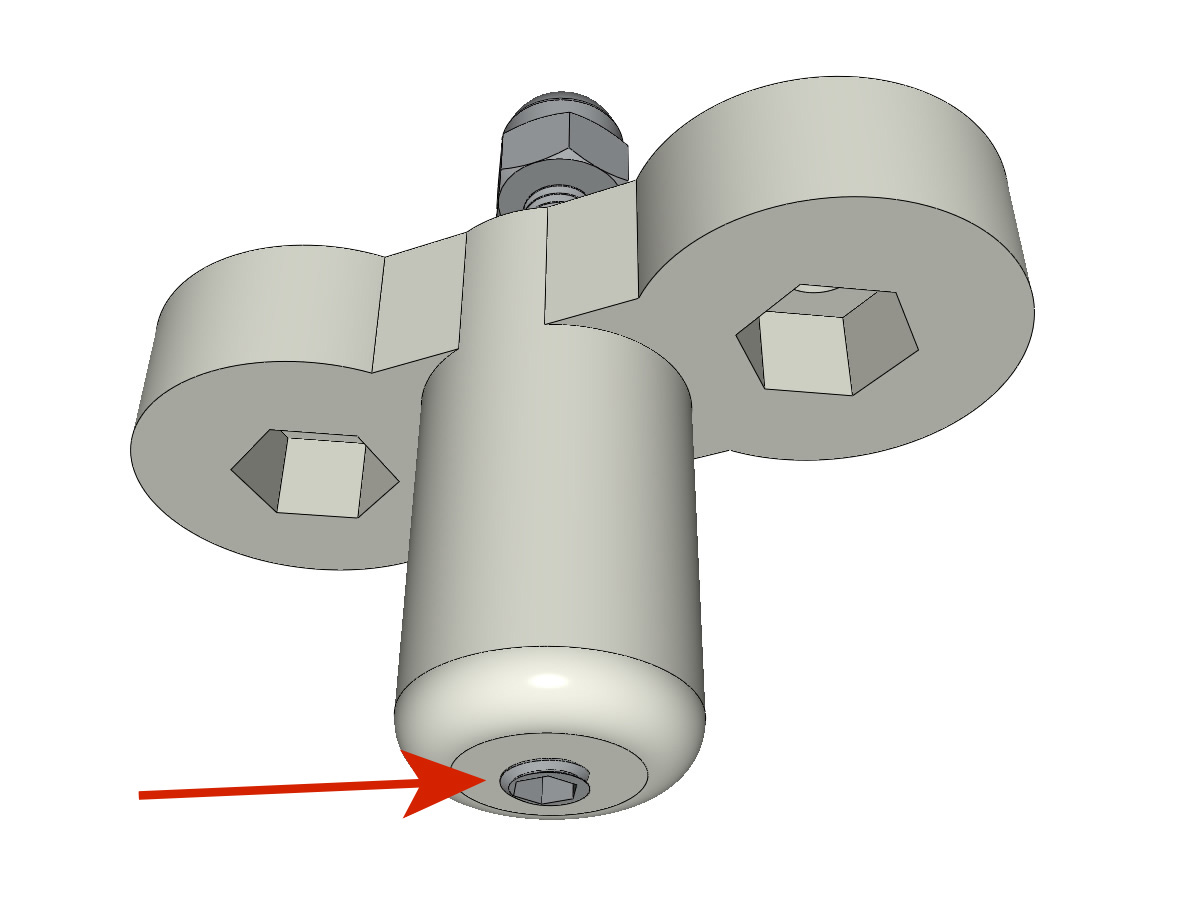
- Center the rollers in the holes of the plate and screw the grub screws until the rollers are firmly attached to the axle.
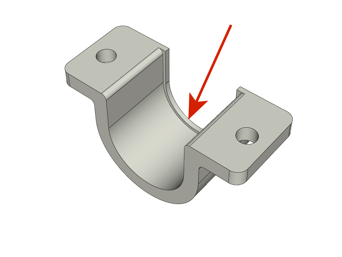
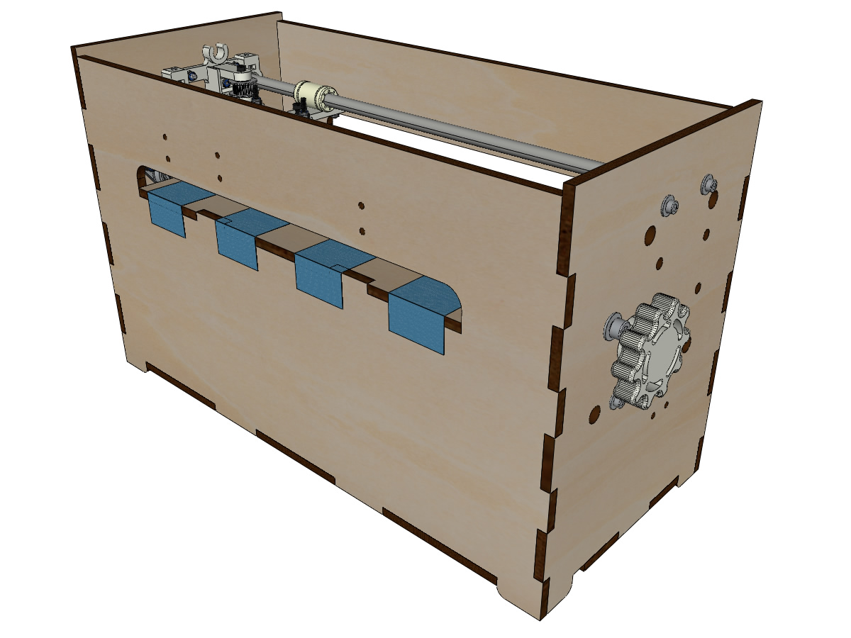
Assembly of the paperweights (step 1):
equipment:
- Assemble the CLIPBOARDs with CLIPBOARD_wheel using M3-20 screws and M3 NYL nuts. Tighten the screw allowing the wheel to turn.
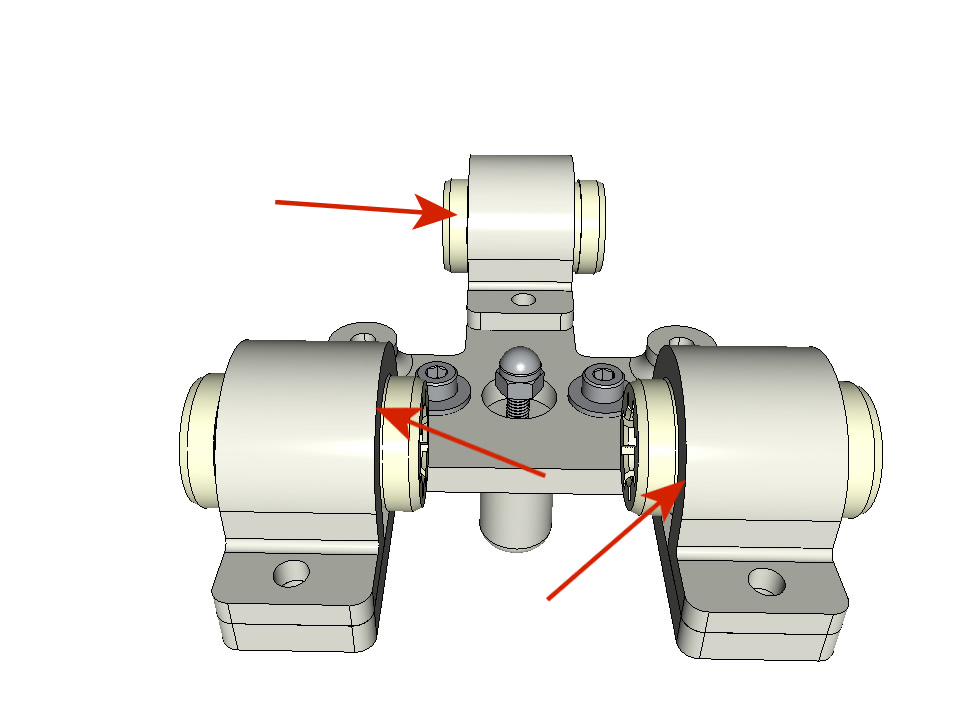
Assembly of the paperweights (step 2):
equipment:
- 2 CLIPBOARD mounted in step 1
- 4 screws M3-14
- 4 medium M3 washers
- 4 NYL M3 nuts
Note
The oblong holes in the printed parts adjust the pressure of the CLIPBOARD on the paper.
Assembly of the Y limit switch
equipment:
- ** Piece (s) printed in 3D **: SWITCH_Y_support
- 2 screws M3-14
- 2 medium M3 washers
- 2 M3 NYL nuts
- 1 slatted limit switch
- 2 screws M2.5-14
- 2 nuts M2.5 NYL
Note
The slat limit switch must be wired before being mounted on its support (not shown).
- Assemble the limit switch and the SWITCH_Y_support using M2.5-14 screws and M2.5 NYL nuts.
Note
The position of the switch in the oblong holes will be adjusted at the end of the assembly and the screws tightened.
- Assemble the limit switch assembly and the SWITCH_Y_support to the body using the M3-14 screws, M3 washers and M3 NYL nuts.
Fixing the clips on the lid
equipment:
- ** Piece (s) printed in 3D **: 2 LID_LOCK
- 4 screws M3-14
- 4 NYL M3 nuts
- Assemble the 2 LID_LOCK on the cover using the M3-14 screws, M3 washers and M3 NYL nuts.
Fixing the plate for the power supply base
equipment:
- ** Piece (s) printed in 3D **: POWER_plate
- 4 screws M3-14
- 4 NYL M3 nuts
- ** ADD PICTURE **
Mounting the electronic card on the cash register
equipment:
- MKS GEN 1.4 card
- 4 spacers M3-10 ** Michel, we will send them to you as soon as we receive them **
- 4 medium M3 washers
- 8 screws M3-10
- Assemble the 4 spacers on the card. ** ADD PICTURE **
- Assemble the card on the crate. ** ADD PICTURE **
Laying the drivers on the electronic board
equipment:
- MKS GEN 1.4 card
- 2 DRV8825 drivers
- 6 riders
- If the card is not supplied already equipped with jumpers, put in the places of the drivers of engines X and Y. ** ADD PICTURE **
- Push the drivers into their slots. ** ADD PICTURE **
Connecting the motors to the board
- to do
Wiring of the electromagnet
- to do
Wiring of limit switches
- to do
Vertical alignment of the two carriages
- to do
- Tighten the pulleys on the vertical axis. ** ADD PICTURE **
Adjusting the depth of the point
- Depending on the material you will use (paper, plastic, aluminum bobbin), you will need to adjust the height of the borrows of the high carriage using the blind nut ** to be developed with examples **